1. Introduction
This manual provides essential information for the safe and effective use of the NYGOXSXA Z-15G series limit travel micro switches. These switches are designed for various industrial and automotive applications requiring precise position detection and control. Please read this manual thoroughly before installation and operation to ensure proper functionality and safety.
2. Safety Information
Always observe the following safety precautions to prevent injury or damage to the product and connected equipment:
- Electrical Hazard: Ensure power is disconnected before installing, wiring, or performing maintenance on the switch.
- Qualified Personnel: Installation and wiring should only be performed by qualified electricians or technicians.
- Voltage and Current Ratings: Do not exceed the specified voltage and current ratings of the switch. Refer to the product specifications for details.
- Environmental Conditions: Avoid exposing the switch to extreme temperatures, humidity, dust, or corrosive environments unless specifically rated for such conditions.
- Secure Mounting: Ensure the switch is securely mounted to prevent accidental movement or dislodgement during operation.
3. Product Overview
The NYGOXSXA Z-15G series includes various models of limit travel micro switches, each designed with specific actuator types and electrical characteristics to suit diverse applications. These switches are commonly used for detecting the presence or absence of an object, limiting mechanical travel, or as safety interlocks.

Figure 3.1: Various models within the Z-15G series, showcasing different actuator types and housing designs.
Common variants include models with plunger actuators (e.g., Z-15G-B, Z-15GD-B), roller plunger actuators (e.g., Z-15GQ-B, Z-15GQ22-B), and lever actuators (e.g., Z-15GW2-B, Z-15GW22-B). Each model is designed for specific mechanical interaction and operational requirements.

Figure 3.2: A Z-15GQ22-B model, featuring a roller plunger actuator, suitable for applications requiring smooth activation by moving parts.

Figure 3.3: A Z-15GD-B model, equipped with a standard plunger actuator, ideal for direct contact applications.
4. Setup and Installation
Proper installation is crucial for the reliable operation of the micro switch. Follow these general guidelines:
- Mounting Location: Select a mounting location that allows for consistent and reliable actuation by the target object. Consider environmental factors such as temperature, vibration, and potential for impact.
- Secure Mounting: Use appropriate fasteners (screws, bolts) to firmly attach the switch to a stable surface. Ensure the mounting holes align with the switch's base. Refer to the dimensional drawings for precise hole spacing.
- Wiring:
- Identify the terminals: Typically, micro switches have Common (C), Normally Open (NO), and Normally Closed (NC) terminals.
- Connect the power supply and load according to your circuit diagram. Ensure correct polarity if applicable.
- Use appropriate wire gauges for the current rating.
- Ensure all connections are secure and insulated to prevent short circuits.
- Actuator Adjustment: Adjust the position of the switch or the activating mechanism to ensure the actuator is depressed or released correctly at the desired point of travel. Avoid over-traveling the actuator beyond its mechanical limits.
- Testing: After installation, perform functional tests to verify the switch operates as intended before applying full power or integrating into a larger system.
5. Operating Principles
A limit travel micro switch operates based on a snap-action mechanism. When the actuator is depressed by an external force (e.g., a moving part), it causes the internal contacts to rapidly change state. This rapid change ensures a clean break or make, minimizing arcing and extending the switch's lifespan.
- Normally Open (NO): The circuit is open (no current flow) when the actuator is in its resting position. It closes (current flows) when the actuator is depressed.
- Normally Closed (NC): The circuit is closed (current flows) when the actuator is in its resting position. It opens (no current flow) when the actuator is depressed.
- Common (C): This is the terminal to which the power source is typically connected.
The choice between NO and NC depends on the specific application requirements, such as whether you need a signal when an object is present or absent, or for fail-safe operations.
6. Maintenance
NYGOXSXA micro switches are designed for durability and require minimal maintenance. However, periodic checks can help ensure long-term reliability:
- Visual Inspection: Regularly inspect the switch for any signs of physical damage, corrosion, or loose connections.
- Actuator Check: Ensure the actuator moves freely and returns to its resting position without obstruction. Clean any debris that might interfere with its movement.
- Mounting Security: Verify that the switch remains securely mounted and that mounting screws are tight.
- Environmental Protection: If the switch is in a harsh environment, ensure any protective covers or enclosures are intact and functioning.
- Cleaning: If necessary, gently clean the exterior of the switch with a dry, soft cloth. Avoid using harsh chemicals or solvents.
7. Troubleshooting
If the micro switch is not functioning as expected, consider the following troubleshooting steps:
- No Output/Incorrect Signal:
- Check wiring connections for looseness or incorrect terminal assignment (NO/NC).
- Verify power supply to the circuit.
- Ensure the actuator is being fully depressed or released by the target object. Adjust mechanical alignment if needed.
- Test the switch continuity with a multimeter (with power disconnected) to confirm internal contact operation.
- Intermittent Operation:
- Check for loose wiring or poor contact at terminals.
- Inspect for excessive vibration at the mounting point.
- Ensure the actuator is not sticking or being partially actuated.
- Physical Damage:
- If the switch housing or actuator is visibly damaged, replace the unit.
- Do not attempt to repair internal components.
8. Specifications
The following table provides general specifications for the NYGOXSXA Z-15G series micro switches. Specific ratings may vary by model. Always refer to the markings on your specific switch for precise details.
| Feature | Specification |
|---|---|
| Brand | NYGOXSXA |
| Model Series | Z-15G Series (e.g., Z-15G-B, Z-15GD-B, Z-15GQ-B, Z-15GW22-B) |
| Electrical Rating | Typically 15A 125/250/480VAC, 1/8HP 125VAC, 1/4HP 250VAC, 1/2A 125VDC, 1/4A 250VDC |
| Contact Configuration | SPDT (Single Pole Double Throw) - 1NO, 1NC |
| Actuator Type | Plunger, Roller Plunger, Lever (varies by specific model) |
| Housing Material | Typically durable plastic or phenolic resin |
| Operating Temperature | Standard industrial range (e.g., -25°C to +80°C) |
| Mechanical Life | High (e.g., 1,000,000 operations minimum) |
| Electrical Life | High (e.g., 100,000 operations minimum at rated load) |
| Package Dimensions | 0.39 x 0.39 x 0.39 inches (approximate, varies by model) |
| Item Weight | 1.76 ounces (approximate, varies by model) |
Dimensional Drawings
Refer to the following diagrams for typical dimensions. Note that dimensions may vary slightly between specific models and actuator types.

Figure 8.1: Typical dimensions for a Z-15GS-B type micro switch, showing mounting holes and actuator travel.
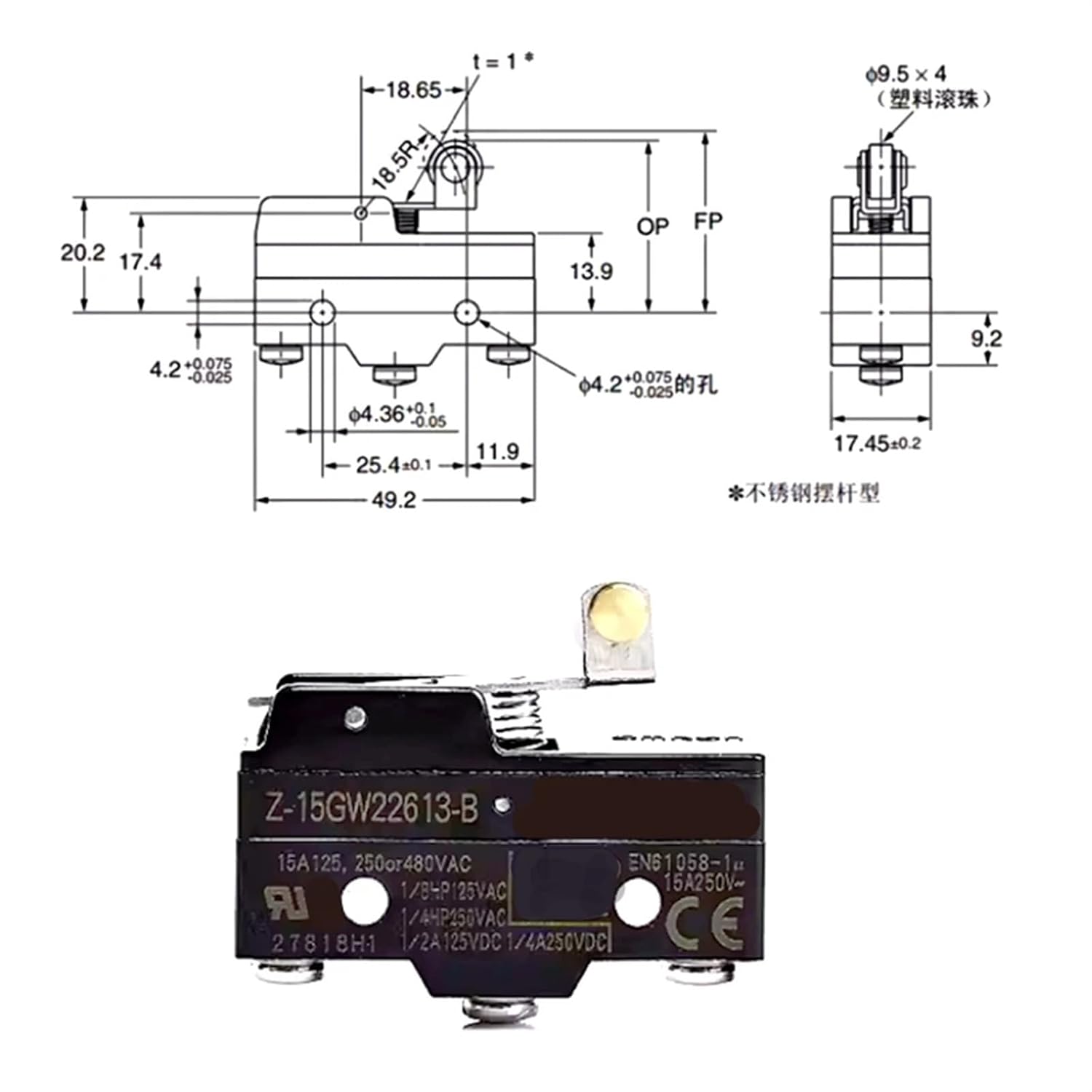
Figure 8.2: Typical dimensions for a Z-15GW22613-B type micro switch, illustrating the lever actuator and overall housing dimensions.
9. Warranty and Support
For warranty information, technical support, or inquiries regarding your NYGOXSXA Z-15G series micro switch, please contact the manufacturer or your authorized distributor. Keep your purchase receipt as proof of purchase.
Manufacturer: NYGOXSXA
Date First Available: May 3, 2025