EFUZCOCI MS8217
EFUZCOCI MS8217 Digital Multimeter User Manual
Model: MS8217
1. Introduction
The EFUZCOCI MS8217 is a versatile digital multimeter designed for accurate measurement of AC/DC voltage, AC/DC current, resistance, capacitance, frequency, duty cycle, and temperature. This manual provides essential information for safe and effective operation of the device.
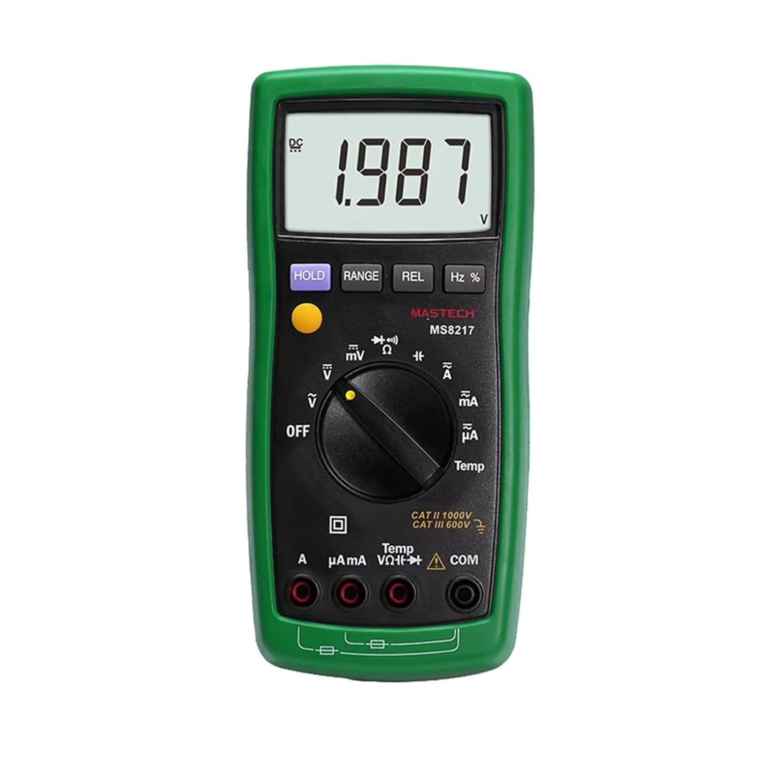
Figure 1: Front view of the EFUZCOCI MS8217 Digital Multimeter with a voltage reading on the display.
2. Safety Information
Always adhere to safety precautions when using electrical testing equipment. Failure to do so may result in electric shock, injury, or damage to the meter or equipment under test.
- Do not exceed the maximum input values specified for each measurement range.
- Ensure the test leads are properly connected and in good condition before use.
- Never measure voltage on circuits with power exceeding the meter's rated capacity.
- Exercise caution when working with voltages above 30V AC RMS, 42V peak, or 60V DC, as these pose a shock hazard.
- Always disconnect power to the circuit and discharge all high-voltage capacitors before measuring resistance, capacitance, or diode.
- Replace batteries when the low battery indicator appears to ensure accurate readings.
- Refer to the "WARNING" label inside the battery compartment for fuse specifications and battery type.
3. Package Contents
Verify that all items are present in the package:
- EFUZCOCI MS8217 Digital Multimeter
- Test leads (Red and Black)
- K-type thermocouple
- Multi-Function Socket
- User's manual

Figure 2: The MS8217 Multimeter alongside its standard accessories.
4. Setup
4.1 Battery Installation
- Ensure the multimeter is powered off.
- Locate the battery compartment cover on the back of the meter.
- Unscrew the retaining screw(s) and remove the cover.
- Insert three 1.5V AAA batteries, observing correct polarity.
- Replace the battery compartment cover and secure it with the screw(s).

Figure 3: Battery compartment with AAA batteries installed.
4.2 Connecting Test Leads
- Insert the red test lead into the "VΩHz" or "mA" or "A" input jack, depending on the measurement function.
- Insert the black test lead into the "COM" (common) input jack.
- Ensure connections are firm before proceeding with measurements.
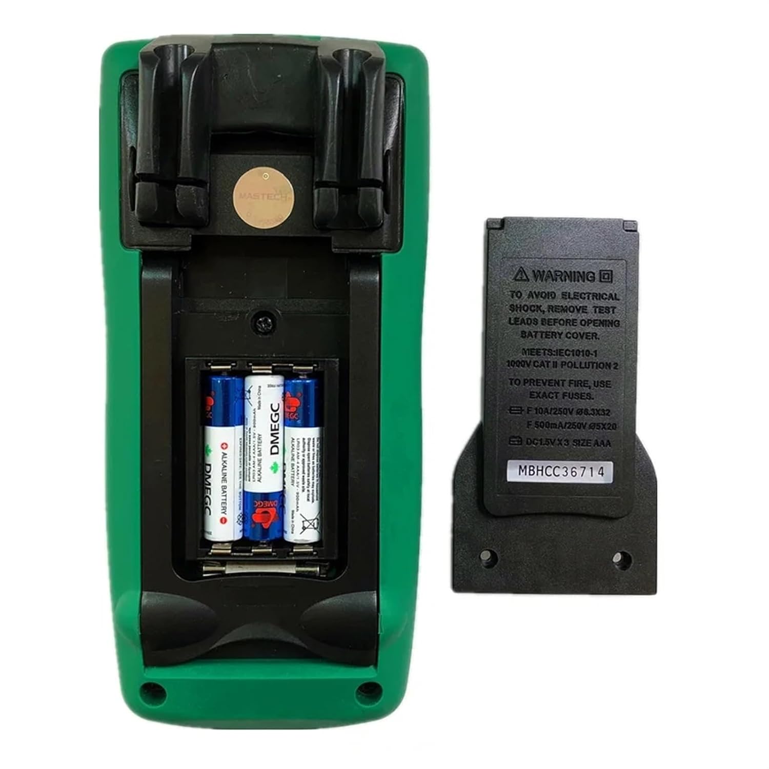
Figure 4: Test leads for the multimeter.
5. Operating Instructions
5.1 Power On/Off
Rotate the function switch to any desired measurement position to power on the meter. To power off, rotate the function switch to the "OFF" position.
5.2 Auto and Manual Ranging
The MS8217 supports both auto and manual ranging. In auto-ranging mode, the meter automatically selects the appropriate range for the measurement. Press the RANGE button to switch between auto and manual ranging. In manual ranging, press RANGE repeatedly to cycle through available ranges.
5.3 Data Hold (HOLD)
Press the HOLD button to freeze the current reading on the display. Press it again to release the hold function and resume live readings.
5.4 Display Backlight
The display backlight can be activated for better visibility in low-light conditions. Refer to the specific button for backlight activation, usually indicated by a light bulb icon or integrated with another function button (e.g., long press of HOLD).
5.5 Relative Measurement (REL)
Press the REL button to store the current reading as a reference value. Subsequent measurements will be displayed as the difference from this reference value. Press REL again to exit relative mode.
5.6 Auto Power Off
The meter features an auto power-off function to conserve battery life. If no operation is performed for a certain period (typically 15 minutes), the meter will automatically power off. Press any button or rotate the function switch to wake it up.
6. Measurement Functions
Rotate the function switch to select the desired measurement mode.
6.1 DC Voltage Measurement (V–)
- Set the function switch to the V– position.
- Connect the red test lead to the VΩHz jack and the black test lead to the COM jack.
- Connect the test probes across the DC voltage source to be measured.
- Read the voltage value on the display.
6.2 AC Voltage Measurement (V∼)
- Set the function switch to the V∼ position.
- Connect the red test lead to the VΩHz jack and the black test lead to the COM jack.
- Connect the test probes across the AC voltage source to be measured.
- Read the voltage value on the display.
6.3 DC Current Measurement (A–, mA–, µA–)
- Set the function switch to the appropriate A–, mA–, or µA– position.
- For current up to 400mA, connect the red test lead to the mA jack. For current up to 10A, connect the red test lead to the A jack. Connect the black test lead to the COM jack.
- Open the circuit where current is to be measured and connect the meter in series with the load.
- Read the current value on the display.

Figure 5: Multimeter set to measure milliamperes.
6.4 AC Current Measurement (A∼, mA∼, µA∼)
- Set the function switch to the appropriate A∼, mA∼, or µA∼ position.
- For current up to 400mA, connect the red test lead to the mA jack. For current up to 10A, connect the red test lead to the A jack. Connect the black test lead to the COM jack.
- Open the circuit where current is to be measured and connect the meter in series with the load.
- Read the current value on the display.
6.5 Resistance Measurement (Ω)
- Set the function switch to the Ω position.
- Connect the red test lead to the VΩHz jack and the black test lead to the COM jack.
- Ensure the circuit is de-energized and all capacitors are discharged.
- Connect the test probes across the component to be measured.
- Read the resistance value on the display.
6.6 Capacitance Measurement (F)
- Set the function switch to the capacitance position (often shared with diode/resistance).
- Connect the red test lead to the VΩHz jack and the black test lead to the COM jack.
- Ensure the capacitor is fully discharged before connecting the probes.
- Connect the test probes across the capacitor.
- Read the capacitance value on the display.
6.7 Frequency (Hz) and Duty Cycle (%) Measurement
- Set the function switch to the Hz % position.
- Connect the red test lead to the VΩHz jack and the black test lead to the COM jack.
- Connect the test probes across the signal source.
- Press the Hz % button to toggle between frequency and duty cycle display.
- Read the value on the display.
6.8 Temperature Measurement (Temp)
- Set the function switch to the Temp position.
- Connect the K-type thermocouple to the appropriate input jacks (usually marked with Temp or specific thermocouple symbols).
- Place the thermocouple probe at the point where temperature is to be measured.
- Read the temperature value on the display.
6.9 Diode Test (→|•))
- Set the function switch to the diode test position (often shared with continuity).
- Connect the red test lead to the VΩHz jack and the black test lead to the COM jack.
- Connect the red probe to the anode and the black probe to the cathode of the diode.
- The display will show the forward voltage drop. Reverse the probes; the display should show "OL" (Open Loop) for a good diode.
7. Maintenance
7.1 Battery Replacement
When the low battery indicator appears on the display, replace the batteries as described in Section 4.1. Use three 1.5V AAA batteries.
7.2 Cleaning
Wipe the meter's casing with a damp cloth and a mild detergent. Do not use abrasives or solvents. Ensure the meter is completely dry before use.
7.3 Fuse Replacement
If the current measurement function fails, the fuse may need replacement. Refer to the warning label inside the battery compartment for the correct fuse specifications (e.g., F 10A/250V Ø6x32, F 500mA/250V Ø5x20). Always replace with a fuse of the identical type and rating.
8. Troubleshooting
- No Display: Check battery installation and ensure batteries are not depleted.
- Incorrect Readings: Verify correct function selection, proper test lead connection, and ensure the circuit is de-energized for resistance/capacitance measurements. Check for low battery.
- "OL" or "OPEN" on Display: Indicates an open circuit, out-of-range measurement, or incorrect connection.
- Current Measurement Not Working: Check the fuse as described in Section 7.3.
9. Specifications
| Measurement | Range | Resolution | Accuracy |
|---|---|---|---|
| DC Voltage | 400mV, 4V/40V/400V/1000V | 0.1mV, 1mV/10mV/100mV/1V | ±(1.0%+10), ±(0.5%+3) |
| AC Voltage | 400mV, 4V/40V/400V/1000V | 0.1mV, 1mV/10mV/100mV/1V | ±(3.0%+3), ±(1.0%+3) |
| DC Current | 400µA/4000µA/40mA/400mA/4A/10A | 0.1µA/1µA/10µA/0.1mA/1mA/10mA | ±(1.5%+3), ±(1.5%+3) |
| AC Current | 400µA/4000µA/40mA/400mA/4A/10A | 0.1µA/1µA/10µA/0.1mA/1mA/10mA | ±(1.5%+3), ±(1.5%+3) |
| Resistance | 400Ω, 4k/40k/400k/4MΩ, 40MΩ | 0.1Ω, 1Ω/10Ω/100Ω/1kΩ, 10kΩ | ±(0.5%+3), ±(0.5%+2), ±(1.5%+3) |
| Capacitance | 50nF, 500nF/5µF/50µF/100µF | 10pF, 100pF/1nF/10nF/100nF | ±(3.0%+10), ±(3.0%+5) |
| Frequency | 50Hz/500Hz/5kHz/50kHz/100kHz | 0.01Hz/0.1Hz/1Hz/10Hz/0.1kHz | ±(0.1%+3), ±(0.1%+3) |
| Duty Cycle | 0.1%~99% | 0.1% | ±(2.0%+5) |
| Temperature | -55~0°C, 1~400°C, 401~1000°C | 0.1°C, 0.1°C, 1°C | ±(9.0%+2), ±(2.0%+1), ±(2.0%) |
General Specifications:
- Display: 4000 counts
- Power Supply: 3 x 1.5V AAA Batteries (not included)
- Product Size: 185mm x 87mm x 53mm (7.28" x 3.4" x 2.04")
- Product Weight: 360g (0.79lb)
- Diode Open Voltage: 1.5V
- Low Battery Display: Yes
- Display Backlight: Yes
10. Warranty and Support
For warranty information or technical support, please contact EFUZCOCI customer service through the retailer where the product was purchased. Keep your purchase receipt as proof of purchase.
Ask a question about this manual
Ask about setup, troubleshooting, compatibility, parts, safety, or missing instructions. Manuals+ will review the question and use this page’s manual context to help answer it.