1. Introduction
The NYGOXSXA UT60BT is a True RMS digital multimeter designed for accurate measurement of AC/DC voltage, AC/DC current, resistance, capacitance, frequency, duty cycle, and temperature. It features Non-Contact Voltage (NCV) detection, diode testing, and continuity testing. This manual provides essential information for safe and effective operation of the device.
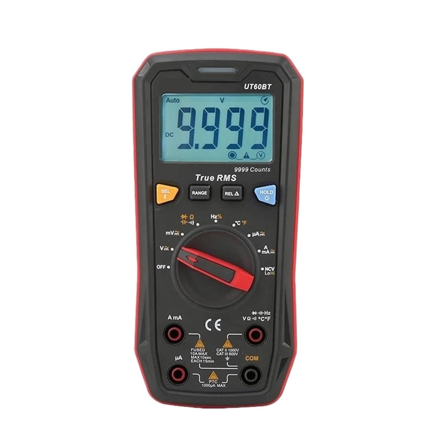
Figure 1.1: Front view of the NYGOXSXA UT60BT Digital Multimeter, showing the display, rotary switch, and input jacks.
2. Safety Information
To ensure safe operation and service of the meter, follow these safety guidelines:
- Always adhere to local and national safety codes.
- Do not use the meter if it appears damaged or if the insulation on test leads is compromised.
- Verify the meter's operation by measuring a known voltage or current before use.
- Do not apply more than the rated voltage, as marked on the meter, between terminals or between any terminal and earth ground.
- Use caution when working with voltages above 30V AC RMS, 42V peak, or 60V DC. These voltages pose a shock hazard.
- Remove test leads from the circuit before changing functions or ranges.
- Replace the battery as soon as the low battery indicator appears to avoid incorrect readings.
- Do not operate the meter in explosive gas, vapor, or dust environments.
3. Product Features
The UT60BT Digital Multimeter offers a range of advanced features for electrical testing:
- True RMS Measurement: Provides accurate readings for non-sinusoidal waveforms.
- NCV Testing: Non-Contact Voltage detection for identifying live wires without direct contact.
- Max Display: 9999 counts for high-resolution measurements.
- Full Function Protection: Built-in overload protection across all ranges.
- Versatile Measurements: Measures AC/DC Voltage, AC/DC Current, Resistance, Capacitance, Frequency, Duty Cycle, and Temperature.
- Data Hold: Freezes the displayed reading for convenient recording.
- Relative Mode (REL): Measures the difference between a stored reference value and a new measurement.

Figure 3.1: Visual representation of the UT60BT's key features, including True RMS, NCV Testing, and 9999 Max Display.
4. Setup
4.1 Battery Installation
- Ensure the multimeter is powered off and test leads are disconnected.
- Locate the battery compartment cover on the rear of the meter.
- Unscrew the retaining screw(s) and remove the cover.
- Insert the required batteries (typically AA or 9V, refer to the battery compartment label) observing correct polarity.
- Replace the battery compartment cover and secure it with the screw(s).
4.2 Connecting Test Leads
- Insert the black test lead into the COM (common) input jack.
- For voltage, resistance, capacitance, frequency, and temperature measurements, insert the red test lead into the VΩHz™ input jack.
- For current measurements (mA/µA), insert the red test lead into the mAµA input jack.
- For high current measurements (10A), insert the red test lead into the 10A input jack.
5. Operating Instructions
5.1 General Operation
- Power On/Off: Rotate the central switch from OFF to any measurement function to power on. Rotate back to OFF to power off.
- Function Selection: Use the rotary switch to select the desired measurement function (e.g., V∼, V−, A∼, A−, Ω, etc.).
- SEL Button: Used to switch between different measurement types within a single rotary switch position (e.g., AC/DC voltage, resistance/continuity/diode).
- RANGE Button: Manually selects the measurement range. Press and hold to return to auto-ranging.
- REL∆ Button: Activates relative mode, displaying the difference from a stored reference value.
- HOLD Button: Freezes the current display reading. Press again to release.
5.2 Voltage Measurement (AC/DC)
- Set the rotary switch to V∼ (AC Voltage) or V− (DC Voltage). If the symbol is combined, use the SEL button to toggle between AC and DC.
- Connect the red test lead to the VΩHz™ jack and the black test lead to the COM jack.
- Connect the test probes in parallel to the circuit or component under test.
- Read the voltage value on the display.
5.3 Current Measurement (AC/DC)
- Set the rotary switch to A∼ (AC Current) or A− (DC Current) for Amperes, or mA∼/mA− or µA∼/µA− for milli/microamperes. Use SEL to toggle AC/DC if combined.
- Connect the black test lead to the COM jack.
- For mA/µA, connect the red test lead to the mAµA jack. For 10A, connect the red test lead to the 10A jack.
- Important: Connect the meter in series with the circuit. Open the circuit and insert the meter.
- Read the current value on the display.
5.4 Resistance Measurement
- Set the rotary switch to Ω.
- Connect the red test lead to the VΩHz™ jack and the black test lead to the COM jack.
- Ensure the circuit is de-energized before measuring resistance.
- Connect the test probes across the component to be measured.
- Read the resistance value on the display.
5.5 Capacitance Measurement
- Set the rotary switch to •• (Capacitance symbol, often shared with diode/continuity). Use SEL to select capacitance.
- Connect the red test lead to the VΩHz™ jack and the black test lead to the COM jack.
- Ensure the capacitor is fully discharged before measurement to prevent damage to the meter.
- Connect the test probes across the capacitor terminals.
- Read the capacitance value on the display.
5.6 Frequency/Duty Cycle Measurement
- Set the rotary switch to Hz%.
- Connect the red test lead to the VΩHz™ jack and the black test lead to the COM jack.
- Connect the test probes in parallel to the circuit where frequency or duty cycle is to be measured.
- Use the SEL button to toggle between frequency (Hz) and duty cycle (%).
- Read the value on the display.
5.7 Temperature Measurement
- Set the rotary switch to ™C/™F.
- Connect the temperature probe (thermocouple) to the VΩHz™ and COM jacks, observing polarity if applicable.
- Place the tip of the temperature probe on or near the object whose temperature is to be measured.
- Use the SEL button to toggle between Celsius (™C) and Fahrenheit (™F).
- Read the temperature value on the display.
5.8 Non-Contact Voltage (NCV) Detection
- Set the rotary switch to NCV.
- Move the top part of the meter (NCV sensor area) close to the conductor or outlet.
- The meter will indicate the presence of AC voltage through an audible beep and/or visual indicator (LEDs).
6. Maintenance
6.1 Cleaning
Wipe the case with a damp cloth and mild detergent. Do not use abrasives or solvents. Ensure the meter is completely dry before use.
6.2 Battery Replacement
When the low battery indicator appears on the display, replace the batteries as described in Section 4.1. Use only the specified battery type.
6.3 Fuse Replacement
If the current measurement function fails, the fuse may need replacement. Refer to the meter's internal diagram or contact customer support for specific fuse types and replacement procedures. Always disconnect power and test leads before opening the meter for fuse replacement.
7. Troubleshooting
- No Display/Power: Check battery installation and charge. Ensure the rotary switch is not in the OFF position.
- Incorrect Readings: Verify test lead connections, ensure the correct function and range are selected. Check battery level.
- Current Measurement Not Working: Check the fuse. Ensure test leads are connected to the correct current input jacks (mA/µA or 10A).
- "OL" or "OVER" on Display: Indicates an overload or out-of-range measurement. Select a higher range or ensure the measured value is within the meter's capabilities.
8. Specifications
| Parameter | Value |
|---|---|
| Brand | NYGOXSXA |
| Model | UT60BT |
| Max Display | 9999 Counts |
| Item Weight | 50 Grams |
| Package Dimensions | 0.39 x 0.39 x 0.39 inches |
| Voltage Rating | Up to 1000V AC/DC |
| Measurement Type | True RMS |
9. Warranty and Support
For warranty information, technical support, or service inquiries, please contact your original point of purchase or the manufacturer directly. Keep your purchase receipt as proof of purchase for warranty claims.