ChongXiao WXGN301
ChongXiao WXGN301 Brushless Controller and LCD Display User Manual
Model: WXGN301 | Brand: ChongXiao
Product Overview
This manual provides detailed instructions for the installation, operation, and maintenance of your ChongXiao WXGN301 Brushless Controller and accompanying LCD Display. This system is designed for electric bikes and e-scooters, supporting universal voltage ranges from 36V to 72V and power outputs from 500W to 1000W.

Figure 1: The ChongXiao WXGN301 Brushless Controller and LCD Display kit, including the controller unit, LCD display, and various wiring harnesses.
Installation and Wiring
Careful wiring is essential for proper function and safety. Follow these steps for connecting the controller and LCD display.
Controller Wiring Connections

Figure 2: Detailed view of the controller's wiring harness with numbered labels indicating each connection point.
- Phase Line Connection: Connect the motor's phase lines to the controller's phase lines, matching colors (e.g., green to green, blue to blue, yellow to yellow).
- Hall Line Connection: Connect the motor's Hall sensor lines to the controller's Hall lines, matching colors. Ensure your motor has 5 Hall wires.
- Battery Connection: Connect the battery lines. The red wire is for battery positive (+), and the black wire is for battery negative (-). Ensure correct polarity.
- LCD Line and Ignition Switch: Connect the controller's LCD line. If your throttle does not have an ignition switch, the two ignition wires on the controller must be shorted together to power on the system.
- Intelligent Recognition (Self-Learning):
- Turn off the power.
- Connect the two intelligent recognition lines together.
- Turn on the power. The wheel will rotate forward or reverse.
- If the wheel rotates forward, separate the intelligent recognition lines.
- If the wheel rotates in reverse, separate the intelligent recognition lines, then connect them together again. If the wheel now rotates forward, separate the intelligent recognition lines.
- This function allows the controller to automatically identify the battery voltage and motor rotation direction.
- Note: When using the throttle, the intelligent recognition lines must be separated.
- Other Connections: Connect other functions as needed, such as high-level brake, brake light power, throttle handle, reverse gear, low brake, linear brake (thumb brake), PAS, headlight/taillight power, and regenerative brake. Refer to Figure 2 for connection points.

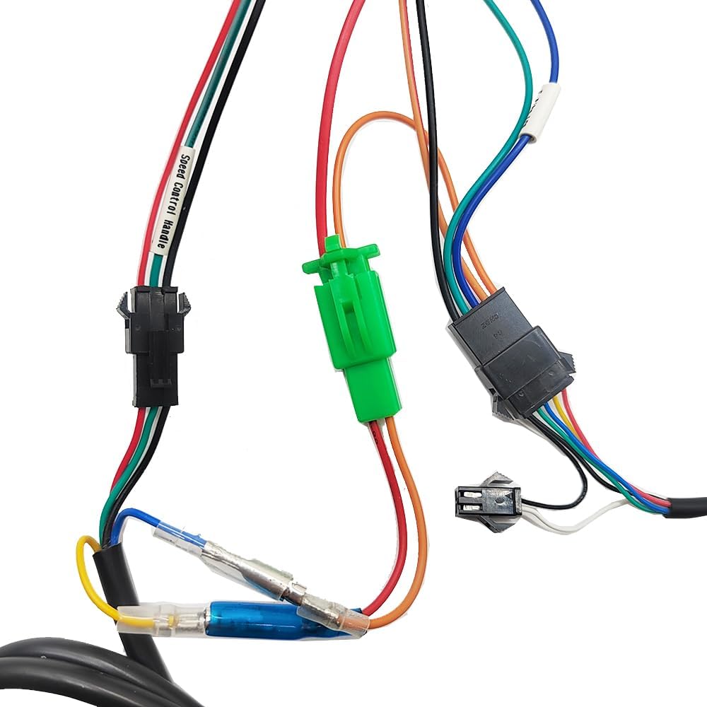
Figure 3: Examples of specific connectors for the LCD display, light power, and speed control handle.
Operating Instructions
LCD Display Overview (WXGN301)
The LCD display communicates with the controller using the UART protocol. It provides real-time riding data and allows for parameter adjustments.

Figure 4: The WXGN301 LCD Display and its integrated control buttons.
LCD 5-Wire Interface
- Red: Meter power cord
- Blue: Power control wire of the controller
- Black: Instrument ground wire
- Green: Data receiving line of the meter
- Yellow: Data transmission line of the meter
Button Introduction
The display features an 'M' (Mode/Power) button, an 'Up' button, and a 'Down' button. Operations are categorized into short press, long press, and combination long press.
- Short Press: Used for quick actions (e.g., changing assist/speed gear, switching display data).
- Single Button Long Press: Used for mode or state switching (e.g., turning display on/off).
- Combination Key Long Press: Used for parameter settings to prevent accidental changes.
Specific Operations
- Power On/Off: Long press the 'M' (power) button to turn the display on or off.
- Switch Display Modes: After the display is on, short press the 'M' button to cycle through different display data (e.g., ODO, Trip, Voltage).
- Modify Assist Ratio/Electric Gear:
- Short press the 'Up' button to increase the assist level.
- Short press the 'Down' button to decrease the assist level.
- Switch Speed Display Mode: Long press the 'M' and 'Up' buttons simultaneously to switch between different speed display modes (e.g., average speed, max speed).
- Turn On/Off Headlights: Long press the 'Up' button to toggle the headlights on or off.
Parameter Settings (P01-P18)
To enter the parameter setting interface, press and hold the 'Up' and 'Down' buttons simultaneously. Use the 'Up' or 'Down' buttons to adjust values. Short press the 'M' button to move to the next parameter. To exit and save, long press 'Up' and 'Down' simultaneously, or the system will auto-save and exit after 10 seconds of inactivity.
| Parameter Code | Description | Range/Notes |
|---|---|---|
| P01 | Backlight Brightness | 0001 (darkest) to 0003 (brightest) |
| P02 | Mileage Unit | 0000: KM; 0001: MILE |
| P03 | Voltage Level | 24V, 36V, 48V, 52V, 60V, 72V (Default: 36V) |
| P04 | Sleep Time | 0: No sleep; 1-60: Sleep time in minutes |
| P05 | Power-Assist Gear | Adjustable: 3rd, 5th, or 9th gears |
| P06 | Wheel Diameter | Unit: inches; Precision: 0.1 |
| P07 | Number of Speed Measuring Magnets | Range: 1-255 |
| P08 | Speed Limit | Range: 0-100 km/h (100 means max speed limit). Note: Displayed mile speed limit may not convert automatically from km/h setting. |
| P09 | Start Mode | 0: Zero start; 1: Non-zero start |
| P10 | Drive Mode Setting | 0000: Power-assisted drive (throttle invalid). 0001: Electric drive (throttle active, assist invalid). 0002: Power-assisted and electric drive coexist (zero start invalid). |
| P11 | Boost Sensitivity | Range: 1-24 |
| P12 | Power-Assisted Start Strength | Range: 1-5 |
| P13 | Power-Assisted Magnetic Steel Discs | 5, 8, or 12 magnets |
| P14 | (0 gear) | Value: 1 (excluding 0 gear) |
| P15 | Cruise Function | Value: 0 (does not cruise) |
| P16 | Total Mileage Reset | ODO reset |
| P17 | Factory Reset | Resets all parameters to default settings. |
| P18 | Default Value | Cannot be changed. |
Note: Due to potential production batch differences, some parameters may vary slightly from this description but will not affect general usage.
Troubleshooting
The LCD display can show error codes to indicate system issues. Refer to the table below for common error codes and their potential solutions.
| Code | Meaning | Suggested Action |
|---|---|---|
| 6 | Battery Undervoltage | Charge the battery or check battery connections. |
| 7 | Motor Failure | Check if the motor Hall sensor has 5 wires and if they are connected color-to-color. Inspect motor wiring for damage. |
| 8 | Throttle Handle Failure | Inspect throttle wiring and ensure it is properly connected. Test throttle functionality. |
| 9 | Controller Failure | Check all controller connections. If the issue persists, the controller may require replacement. |
| 10 | Communication Reception Failure | Check the green data receiving line of the meter and its connection to the controller. |
| 11 | Communication Sending Failure | Check the yellow data transmission line of the meter and its connection to the controller. |
| 12 | BMS Communication Failure | Verify the battery management system (BMS) connection and functionality. |
| 13 | Headlight Failure | Check headlight wiring and bulb/LED. Ensure the headlight power connection is secure. |
Product Specifications
Controller Specifications
- Voltage: 36V / 48V / 52V / 60V / 72V (Universal)
- Current: 26A - 33A
- Number of Transistors: 12
- Rated Power: 500W - 1000W (Compatible)
- Material: Aluminum alloy casing for heat dissipation
- Safety Features: Built-in overvoltage/undervoltage protection, overheating protection, short circuit protection, anti-runaway function.


Figure 5: Controller label detailing voltage and current, and physical dimensions.
LCD Display Specifications (WXGN301)
- Working Voltage: 36V, 48V, 52V, 60V, 72V (Default: 36V, user adjustable)
- Communication Protocol: UART
- Dimensions: Approximately 110mm (length) x 60mm (width)
- Features: High-definition display, real-time speed, battery level, mileage, fault codes, night backlight function.

Figure 6: The WXGN301 LCD Display showing its approximate dimensions.
General Product Information
- Included Components: 1x Brushless Controller, 1x LCD Display
- Color: Red (Controller casing)
- Item Weight: Approximately 862 g
- Manufacturer: Jiangsu Wuxi Bull Technology Co. Ltd
Maintenance
To ensure the longevity and optimal performance of your controller and display, follow these general maintenance guidelines:
- Cleaning: Regularly wipe the controller and display with a soft, dry cloth. Avoid using harsh chemicals or excessive moisture.
- Inspection: Periodically check all wiring connections for looseness or damage. Ensure the controller is securely mounted.
- Environmental Protection: Protect the components from extreme temperatures, direct sunlight, and heavy rain. While the controller has an aluminum alloy casing for heat dissipation, prolonged exposure to harsh conditions can affect performance.
Warranty and Support
For warranty information or technical support, please refer to the documentation provided at the point of purchase or contact your retailer. Keep your purchase receipt as proof of purchase.
no relevant documents
Ask a question about this manual
Ask about setup, troubleshooting, compatibility, parts, safety, or missing instructions. Manuals+ will review the question and use this page’s manual context to help answer it.