1. Introduction
This manual provides essential information for the safe and efficient installation, operation, and maintenance of the HVGZDQQD CL57Y Nema23 Closed Loop Stepper Motor Kit. This kit includes a Nema23 closed-loop stepper motor, a CL57Y stepper driver, and a compatible switching power supply. Please read this manual thoroughly before using the product to ensure proper functionality and to prevent damage or injury.
2. Safety Information
Adherence to the following safety guidelines is crucial for preventing personal injury and damage to the equipment.
- Electrical Safety: Ensure all power connections are made by qualified personnel. Disconnect power before making any wiring changes or performing maintenance. The power supply operates at voltages that can cause electric shock.
- Mechanical Safety: Motors can generate significant torque and heat. Ensure the motor is securely mounted to prevent movement during operation. Keep hands and loose clothing away from moving parts.
- Environmental Conditions: Operate the kit within specified temperature and humidity ranges. Avoid exposure to dust, moisture, corrosive gases, or flammable materials.
- Proper Grounding: Ensure the system is properly grounded to prevent electrical hazards and ensure stable operation.
- Emergency Stop: Implement an accessible emergency stop mechanism in your system design.
3. Package Contents
Verify that all components listed below are present and undamaged upon unpacking:
- 1 x Nema23 Closed Loop Stepper Motor (3.00Nm, 424.83oz.in) with 1000PPR (4000CPR) Encoder
- 1 x CL57Y Closed Loop Stepper Driver (0-7.0A, 24-50VDC)
- 1 x Switching Power Supply (201W, 36V, 5.9A, 115/230V selectable)
4. Product Overview
The HVGZDQQD CL57Y Nema23 Closed Loop Stepper Motor Kit is designed for applications requiring precise position control and high torque, such as 3D printers, CNC machines, and automation equipment. The closed-loop system provides feedback from the encoder to the driver, ensuring accurate positioning and preventing step loss.
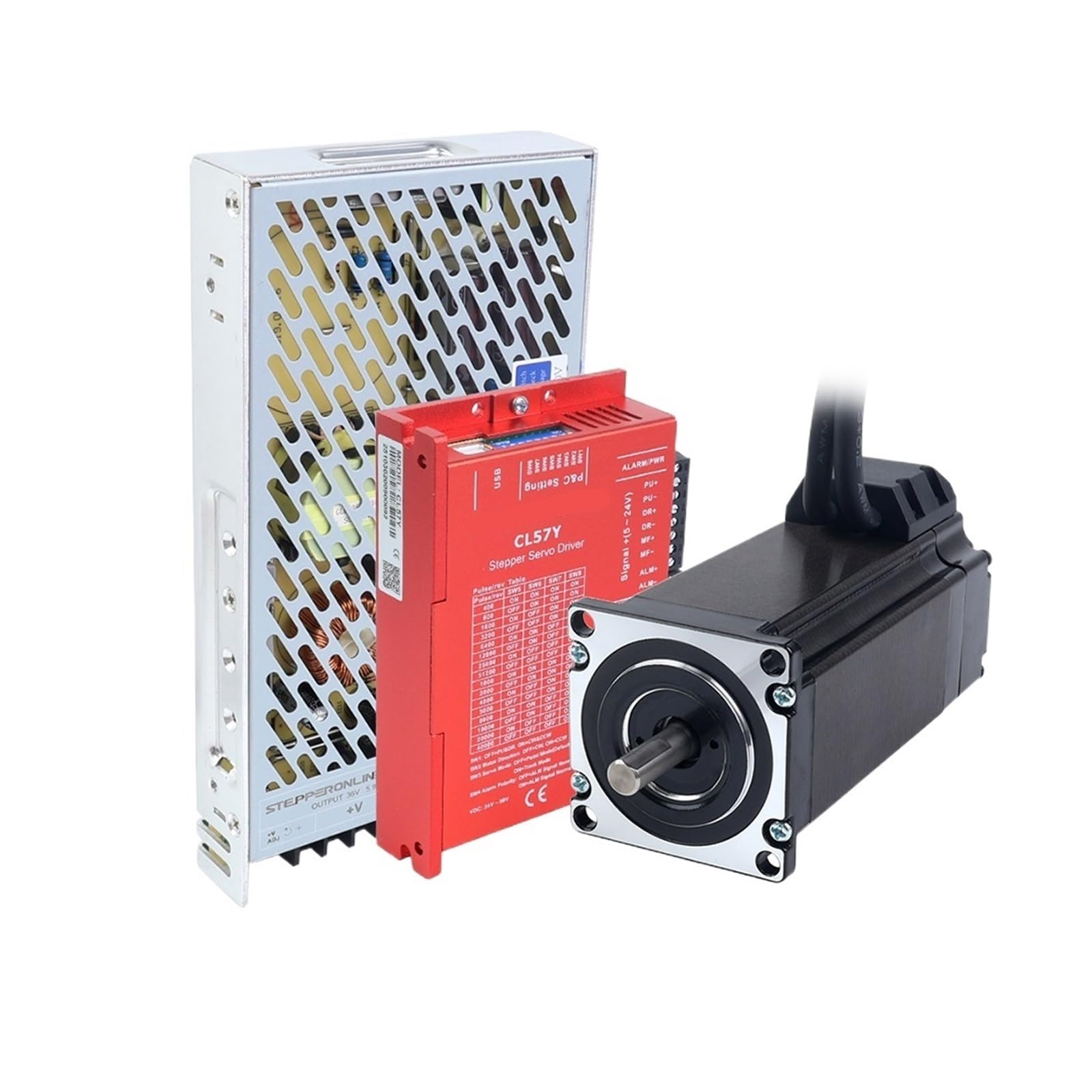
Image 1: Overview of the HVGZDQQD Nema23 Closed Loop Stepper Motor Kit, showing the motor, driver, and power supply.
4.1. Nema23 Closed Loop Stepper Motor
This is a Nema23 frame size stepper motor with an integrated encoder. The encoder provides real-time position feedback to the driver, allowing for closed-loop control. The motor features a 3.00Nm (424.83 oz.in) holding torque and an 8mm shaft diameter.
4.2. CL57Y Closed Loop Stepper Driver
The CL57Y driver is specifically designed to work with closed-loop stepper motors. It interprets control signals (pulse/direction) from a host controller and drives the motor while monitoring the encoder feedback to maintain position accuracy. It supports a current range of 0-7.0A and operates on a DC voltage between 24V and 50V.
4.3. Switching Power Supply
The included power supply converts AC mains voltage (115V/230V selectable) to a stable 36V DC output, providing 5.9A of current, sufficient to power the CL57Y driver and Nema23 motor.
5. Setup
Follow these steps for proper installation and wiring of the motor kit.
5.1. Mounting the Motor
- Select a sturdy, flat surface for mounting the Nema23 motor.
- Align the motor with the mounting holes on your equipment.
- Secure the motor using appropriate screws and washers. Ensure the motor is firmly attached to prevent vibration and misalignment.
5.2. Wiring the Motor to the Driver
Connect the motor phase wires to the corresponding terminals on the CL57Y driver. Refer to the wiring diagram provided with the driver for exact pin assignments. Typically, stepper motors have 4 or 8 wires. For 4-wire motors, connect A+, A-, B+, B-. For 8-wire motors, ensure correct series or parallel connection as per your application and driver specifications.
5.3. Connecting the Encoder to the Driver
The motor's encoder cable connects to the dedicated encoder input port on the CL57Y driver. Ensure the connector is properly oriented and securely seated. Incorrect connection can damage the encoder or driver.
5.4. Connecting the Power Supply to the Driver
- Power Supply Input: Connect the AC mains voltage (115V or 230V) to the input terminals of the switching power supply. Ensure the voltage selector switch on the power supply is set correctly for your region.
- Power Supply Output: Connect the 36V DC output from the power supply to the V+ and V- terminals on the CL57Y driver. Observe correct polarity (V+ to V+, V- to V-).
5.5. Connecting the Driver to the Control System
Connect the pulse (PUL+ / PUL-), direction (DIR+ / DIR-), and enable (ENA+ / ENA-) signals from your host controller (e.g., PLC, microcontroller, CNC controller) to the corresponding input terminals on the CL57Y driver. Ensure common ground connections if using single-ended signals, or proper differential connections if using differential signals.
6. Operating Instructions
Once the kit is fully installed and wired, follow these steps for operation.
6.1. Initial Power-Up
- Double-check all wiring connections for correctness and security.
- Apply AC power to the switching power supply. The power supply indicator light should illuminate.
- The CL57Y driver's status indicator should show a ready state (refer to the driver's specific manual for LED indications).
6.2. Driver Configuration (DIP Switches)
The CL57Y driver typically features DIP switches for setting parameters such as micro-stepping resolution and motor current. Consult the specific CL57Y driver manual for detailed instructions on configuring these settings to match your application requirements. Incorrect settings can lead to poor performance or motor overheating.
6.3. Sending Control Signals
Use your host controller to send pulse and direction signals to the CL57Y driver. The motor will move one step for each pulse received, in the direction specified by the direction signal. The enable signal can be used to activate or deactivate the motor holding torque.
- Pulse (PUL): Controls the number of steps and speed.
- Direction (DIR): Controls the rotation direction of the motor.
- Enable (ENA): Activates or deactivates the motor.
7. Maintenance
Regular maintenance helps ensure the longevity and reliable operation of your motor kit.
- Cleaning: Periodically clean the motor and driver to remove dust and debris. Use a soft, dry cloth or compressed air. Ensure power is disconnected before cleaning.
- Connections Check: Regularly inspect all electrical connections for tightness and signs of wear or corrosion. Re-tighten any loose connections.
- Environmental Check: Ensure the operating environment remains within specified conditions (temperature, humidity, absence of contaminants).
- Motor Shaft: Check the motor shaft for any signs of damage or excessive play.
8. Troubleshooting
Refer to the following common issues and their potential solutions.
| Problem | Possible Cause | Solution |
|---|---|---|
| Motor does not move or moves erratically. |
|
|
| Motor overheats. |
|
|
| Driver error LED is on. |
|
|
9. Specifications
9.1. Nema23 Closed Loop Stepper Motor
- Frame Size: Nema23
- Holding Torque: 3.00Nm (424.83 oz.in)
- Encoder Resolution: 1000 PPR (Pulses Per Revolution), 4000 CPR (Counts Per Revolution)
- Shaft Diameter: 8mm
- Weight: Approximately 200 Grams (motor only)
9.2. CL57Y Closed Loop Stepper Driver
- Input Voltage: 24-50 VDC
- Output Current: 0-7.0A (Peak)
- Control Mode: Pulse/Direction
- Micro-stepping: Configurable via DIP switches
9.3. Switching Power Supply
- Input Voltage: 115V/230V AC (selectable)
- Output Voltage: 36V DC
- Output Current: 5.9A
- Power Output: 201W
10. Warranty and Support
For warranty information and technical support, please refer to the documentation provided with your purchase or contact the manufacturer directly. Keep your purchase receipt as proof of purchase for warranty claims.