SGPWATT SPH8K48SP-P
SUNGOLDPOWER SPH8K48SP-P 8000W 48V Split Phase Solar Inverter User Manual
Model: SPH8K48SP-P | Brand: SGPWATT
Introduction
This manual provides essential instructions for the safe installation, operation, and maintenance of your SUNGOLDPOWER SPH8K48SP-P 8000W 48V Split Phase Solar Inverter. Please read this manual thoroughly before installation and operation to ensure optimal performance and safety. Keep this manual for future reference.
Safety Instructions
Adhering to these safety guidelines is crucial for preventing injury and damage to the equipment.
- Installation must be performed by qualified personnel in accordance with all local and national electrical codes.
- Ensure all power sources, including AC utility, solar PV, and battery, are disconnected before performing any wiring, maintenance, or service.
- Do not attempt to repair the inverter yourself. Refer all servicing to qualified service personnel.
- This inverter is designed for indoor use in a dry, well-ventilated area. Avoid exposure to moisture, dust, and corrosive substances.
- Ensure proper grounding of the inverter as specified in the installation instructions.
- Keep children and unauthorized persons away from the inverter and its connections.
Product Overview
The SUNGOLDPOWER SPH8K48SP-P is an advanced 8000W 48V pure sine wave solar inverter. It integrates dual MPPT solar charge controllers and a high-capacity 200A battery charger. This versatile unit supports both split-phase (120V/240V) and single-phase (120V) AC output, making it suitable for various residential and commercial applications. A built-in WiFi module allows for convenient remote monitoring via a mobile application.
Key Features
- Rated Output Power: 8000W, with a Max Peak Power of 16000W.
- DC Input: 48V for battery bank connection.
- Solar Charge Controllers: Dual MPPTs with a maximum open circuit voltage of 500VDC.
- Battery Charging: Maximum 200A charging current.
- AC Output: Configurable for Split Phase (120V/240V) or Single Phase (120V).
- Waveform: Pure Sine Wave output for sensitive electronics.
- Certification: UL1741 listed for safety and performance.
- Connectivity: Integrated WiFi Module for remote monitoring via APP, and BMS communication (CAN, USB, RS485).
- Battery Compatibility: Supports AGM/Sealed, Gel, Flooded, Lithium batteries, and a User-defined mode.
- Energy Management: Time-slot charging/discharging function for optimized energy use.
- Scalability: Supports parallel operation of up to 6 units for increased power capacity.
Components and Connections

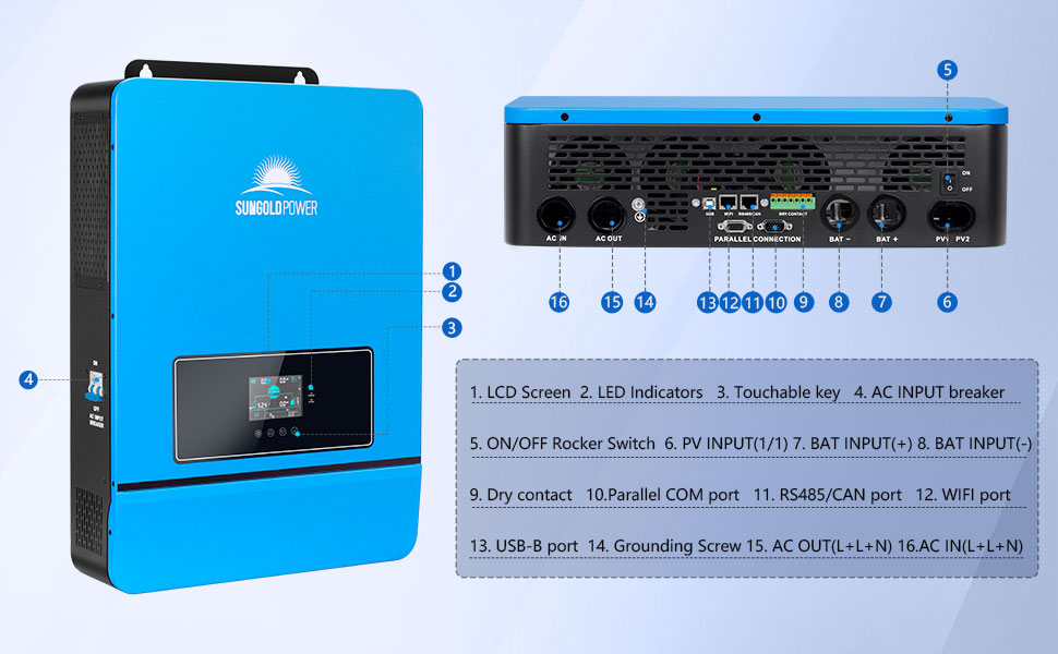
This image displays the SUNGOLDPOWER SPH8K48SP-P inverter from the front and rear, highlighting its various connection ports and indicators. The front panel features an LCD screen, LED indicators, and touchable keys. The rear panel includes the AC input breaker, ON/OFF rocker switch, PV input terminals (PV1, PV2), battery input terminals (BAT+, BAT-), dry contact, parallel COM port, RS485/CAN port, WiFi port, USB-B port, grounding screw, and AC output/input terminals.
- LCD Screen
- LED Indicators
- Touchable Key
- AC Input Breaker
- ON/OFF Rocker Switch
- PV Input (1/1)
- BAT Input (+)
- BAT Input (-)
- Dry Contact
- Parallel COM Port
- RS485/CAN Port
- WiFi Port
- USB-B Port
- Grounding Screw
- AC OUT (L+N)
- AC IN (L+N)
Setup and Installation
Proper installation is critical for the safe and efficient operation of the inverter. All wiring should be performed by a qualified electrician.
Mounting the Inverter
Mount the inverter vertically on a sturdy wall in a well-ventilated area. Ensure the location is free from direct sunlight, excessive heat, moisture, and flammable materials. Maintain adequate clearance around the unit for proper airflow and cooling.

This image illustrates the inverter mounted on a wall, showcasing its integrated LCD HD display for real-time data viewing and parameter settings.
Wiring Connections
Follow these steps for connecting the various components to the inverter. Always ensure power is disconnected before making any connections.
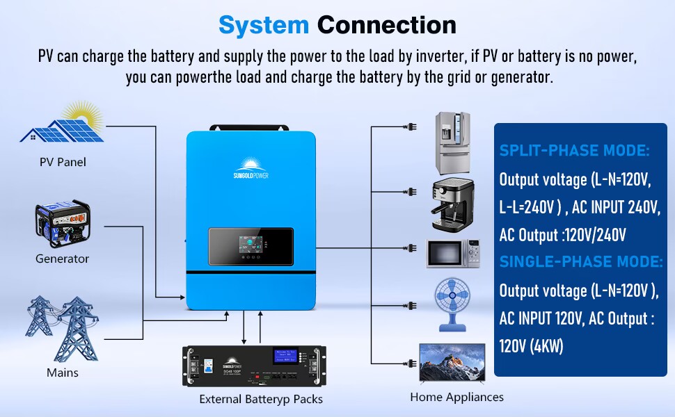
System Connection Overview
This diagram provides an overview of the system connection, showing how PV panels, a generator, mains power, and external battery packs connect to the inverter to supply power to home appliances. It also differentiates between split-phase and single-phase output modes.
Battery Connection
Connect the 48V battery bank to the BAT+ and BAT- terminals on the inverter. Ensure correct polarity (+ to + and - to -) to prevent damage. The inverter is compatible with various battery types, which can be configured in the settings.

This image highlights the inverter's compatibility with multiple battery chemistries: Flooded (FLD), AGM, GEL, Sealed Lead Acid (SLD), LiFePO4 (LI), and User-defined (USER) settings.
PV Array Connection
Connect your solar PV array to the PV1 and PV2 input terminals. Observe the maximum open circuit voltage (500VDC) and current limits specified in the technical specifications to avoid damaging the MPPT controllers.
AC Input/Output Connection
Connect the AC utility grid to the AC IN terminals and your electrical loads to the AC OUT terminals. The inverter supports both 120V/240V split-phase and 120V single-phase configurations. Ensure the wiring matches your desired output mode.

This image clarifies the inverter's AC input and output capabilities, supporting both split-phase (120V/240V output from 240V AC input) and single-phase (120V output from 120V AC input) operations. It also lists key specifications like 11000W Max PV Array Power, 500V Max Open Circuit Voltage, and 200A Max Charge Current.
Parallel Connection (Optional)
For systems requiring higher power output or a three-phase configuration, up to 6 units of the SPH8K48SP-P inverter can be connected in parallel. Refer to the specific wiring diagrams provided in the full manual for detailed instructions on split-phase and three-phase parallel configurations.

This image provides detailed wiring diagrams for parallel connections. It shows configurations for two parallel-connected solar storage inverters for split-phase, and three-phase systems (1+1+1 and 2+2+2 systems) using multiple inverters.
Operating Instructions
Understand how to power on, configure, and utilize the various operating modes of your inverter.
Powering On/Off
- Ensure all wiring is secure and correctly connected.
- Turn on the battery breaker.
- If connected to the utility grid, turn on the AC input breaker.
- If connected to solar panels, turn on the PV array breaker.
- Flip the ON/OFF rocker switch on the inverter to the "ON" position.
- To power off, reverse the sequence: turn off the inverter switch, then PV, then AC input, then battery.
LCD Display and Settings
The integrated LCD HD display provides real-time operating data and allows for parameter configuration. Use the touchable keys to navigate through menus and adjust settings such as battery type, charging priorities, and output voltage.
This image shows a magnified view of the inverter's LCD display, illustrating how real-time data such as PV input, battery voltage, and power output are presented, along with options for parameter adjustment.
Operating Modes
The inverter offers flexible operating modes for both AC output and battery charging to optimize energy management based on your specific needs.

This diagram details the four AC output modes: Utility Priority Output, Solar and Utility Hybrid Output, Solar Priority Output, and Inverter Priority Output. It also shows the four battery charging modes: Hybrid Charging, Utility Priority, Solar Priority, and Only Solar.
AC Output Modes
- Utility Priority Output: The utility grid is the primary power source for loads. The inverter provides power from batteries/solar only when the grid is unavailable.
- Solar and Utility Hybrid Output: Combines solar and grid power to supply loads, prioritizing solar when available.
- Solar Priority Output: Solar power is the primary source for loads. If solar is insufficient, battery power is used, followed by the utility grid.
- Inverter Priority Output: Battery power is the primary source for loads. If battery power is low, solar or grid power is used as a supplement.
Battery Charging Modes
- Hybrid Charging: Charges batteries from both solar and utility power, optimizing charging efficiency.
- Utility Priority Charging: The utility grid is the primary source for charging batteries.
- Solar Priority Charging: Solar power is the primary source for charging batteries.
- Only Solar Charging: Batteries are charged exclusively from solar power.
Time-Slot Charging/Discharging Function
This function allows users to set specific time periods for charging and discharging batteries, enabling optimization based on local peak and valley electricity tariffs. This helps in reducing electricity costs by charging during off-peak hours and discharging during peak hours.
This image illustrates the time-slot charging/discharging function. It includes a graph of peak-valley electricity tariffs and explains how users can set definable periods for utility charging/carrying and battery discharging to optimize energy use and costs.
WiFi Monitoring
The integrated WiFi module enables remote monitoring of the inverter's operating status and parameters via a dedicated mobile application. This allows users to view real-time data, adjust settings, and receive alerts from anywhere with an internet connection.

This image demonstrates the WiFi monitoring capability, showing the inverter connected to a WiFi module and a smartphone displaying real-time data, allowing users to access inverter information remotely.
Maintenance
Regular maintenance ensures the longevity and optimal performance of your inverter.
- Periodic Inspection: Regularly inspect the inverter for any signs of physical damage, loose connections, or unusual noises.
- Ventilation: Keep the ventilation openings clear of dust, debris, and obstructions to ensure proper cooling. Overheating can reduce efficiency and lifespan.
- Cleaning: Clean the exterior of the inverter with a dry, soft cloth. Do not use liquid cleaners, solvents, or abrasive materials.
- Battery Terminals: Periodically check battery terminals for corrosion. If corrosion is present, disconnect power and clean the terminals thoroughly.
- Cable Connections: Ensure all electrical cables are securely fastened and that insulation is intact.
Troubleshooting
This section provides solutions for common issues you might encounter. For problems not listed or if solutions do not resolve the issue, please contact customer support.
| Problem | Possible Cause | Solution |
|---|---|---|
| Inverter not turning on | No battery power; DC breaker off; ON/OFF switch off; faulty wiring. | Check battery connections and voltage; ensure DC breaker and ON/OFF switch are in the 'ON' position. Verify wiring. |
| No AC output | Overload; short circuit on output; AC output breaker tripped; inverter fault. | Reduce connected load; check for short circuits in wiring or appliances; reset AC output breaker. Check inverter display for error codes. |
| No solar charging | PV panels not connected; insufficient sunlight; PV input voltage too low/high; PV breaker off. | Check PV connections and ensure PV breaker is ON; ensure adequate sunlight; verify PV voltage is within the specified operating range. |
| WiFi monitoring not working | WiFi module not connected or faulty; network issues; incorrect APP settings; firewall blocking connection. | Ensure WiFi module is securely connected; check local network connectivity; reconfigure APP settings; consult network administrator for firewall issues. |
| Inverter displaying error code | Internal fault; external condition (e.g., over-temperature, over-voltage). | Note the error code and refer to the full manual's error code section. Power cycle the inverter. If the error persists, contact support. |
Specifications
Detailed technical specifications for the SUNGOLDPOWER SPH8K48SP-P inverter.
| Feature | Specification |
|---|---|
| Model Name | SPH8K48SP-P |
| Rated Power | 8000W |
| Peak Power | 16000W |
| DC Input Voltage | 48V |
| AC Output Voltage | 120V/240V (settable) |
| Max PV Array Power | 11000W |
| Max Open Circuit Voltage | 500VDC |
| Max Charge Current | 200A |
| Product Dimensions | 25.6 x 17.7 x 5.1 inches |
| Item Weight | 53.5 pounds |
| Certifications | UL1741 |
| Communication | WiFi, CAN, USB, RS485 |
| Parallel Capability | Up to 6 units |
Warranty and Support
For detailed warranty information, terms, and conditions, please refer to the warranty card included with your product. For technical support, service, or inquiries, please contact SGPWATT customer service through the contact information provided in your product documentation or on the official SGPWATT website.
What's in the Box
The following items are typically included with your SUNGOLDPOWER SPH8K48SP-P inverter:
- SUNGOLDPOWER SPH8K48SP-P Inverter
- WiFi module
- User Manual
- Warranty Card
- Parallel COM Cable
- Communication Cable
- Cable Lugs & Screws

This image displays the inverter along with its complete set of accessories, including the user manual, warranty card, WiFi module, various cables, and installation hardware.