PowMr B-POW-M60-ULTRA
PowMr 60A MPPT Solar Charge Controller User Manual
Model: B-POW-M60-ULTRA
1. Introduction
This user manual provides comprehensive instructions for the installation, operation, and maintenance of the PowMr 60A MPPT Solar Charge Controller. This controller is designed to efficiently manage power from your solar panels to charge various battery types, including lead-acid and lithium batteries, in 12V, 24V, 36V, and 48V systems. It features advanced Maximum Power Point Tracking (MPPT) technology to maximize energy harvest from your solar array.
2. Safety Information
Please read all instructions and warnings carefully before installation and operation. Failure to follow these instructions may result in electric shock, fire, or severe injury.
- Ensure all wiring is performed by qualified personnel and complies with local electrical codes.
- Always disconnect the solar array and battery power before installing or adjusting the controller.
- Do not disassemble or attempt to repair the controller. Contact customer support for assistance.
- Install the controller in a well-ventilated area, away from flammable materials and direct sunlight.
- The controller features a negative grounding design for added safety.
3. Product Overview
3.1 Key Features
- Rated battery charging current: 60A (configurable from 2A to 60A).
- Rated load output current: 25A.
- Supports 12V, 24V, 36V, and 48V auto-sensing systems.
- Maximum input power: 720W (12V), 1440W (24V), 2100W (36V), 2800W (48V).
- Compatible with various battery types: Sealed, Gel, Flooded, Li (LFP), and user-customized.
- Full charging protections: Short Circuit, Overcurrent, Reverse Polarity.
- Detailed LCD screen and 4-button interface for easy operation.
- Parallel capability: Up to 12 units can be connected in parallel to boost system capacity.
3.2 Appearance Description
The following diagram illustrates the main components and interfaces of the PowMr 60A MPPT Solar Charge Controller.

Figure 3.2.1: Controller Components
- PV Parameters
- PV Parameters
- Battery Parameters
- Load Parameters
- Save/Restore
- Mounting Hole
- Solar Module "+" Interface
- Solar Module "-" Interface
- Battery "+" Interface
- Battery "-" Interface
- Load "+" Interface
- Load "-" Interface
4. Technical Specifications
The following table details the technical specifications for the PowMr 60A MPPT Solar Charge Controller.
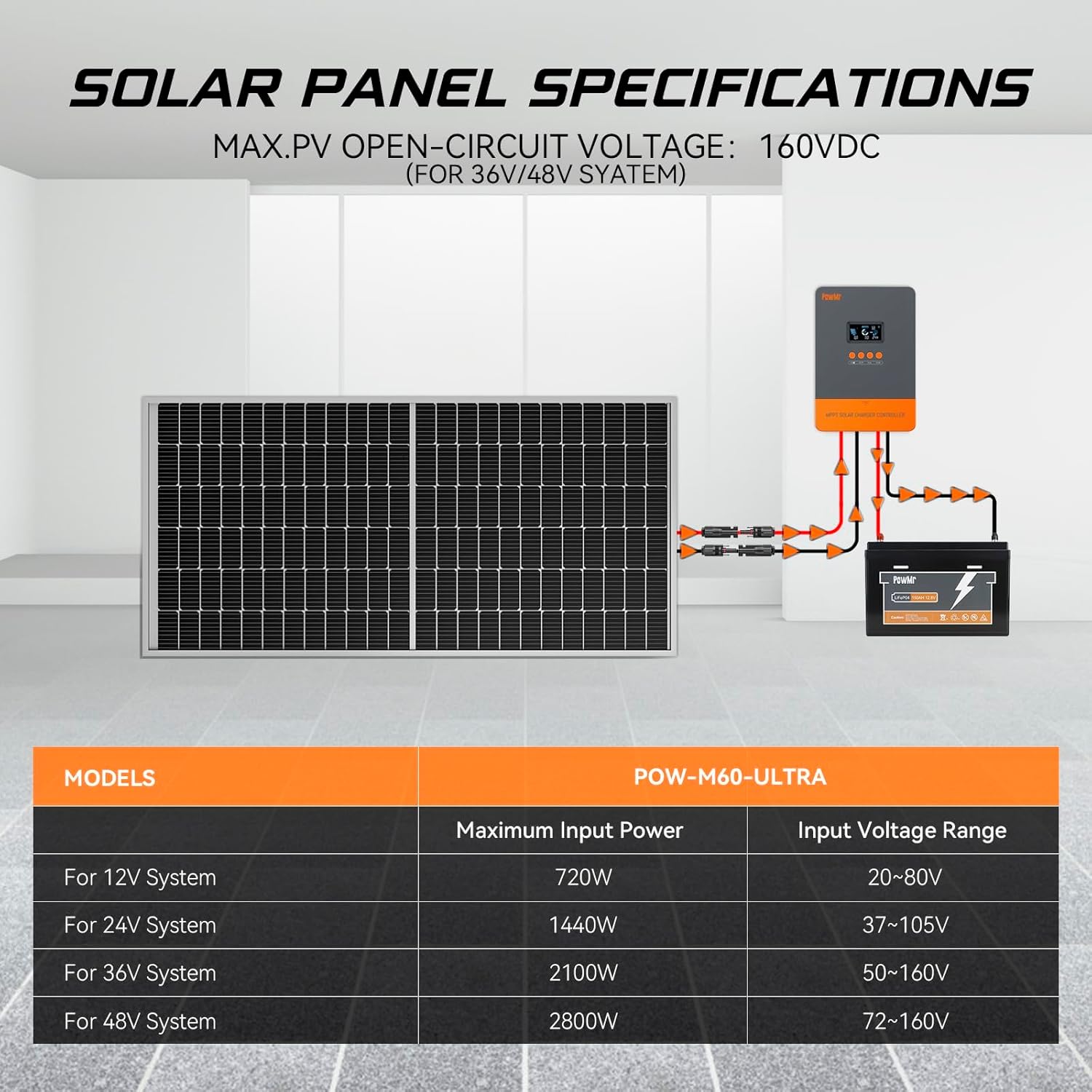
Figure 4.1: Solar Panel Specifications
| Parameter | Value |
|---|---|
| Rated Battery Charging Current | 60A (Configurable 2A-60A) |
| Rated Load Output Current | 25A |
| System Voltage | 12V/24V/36V/48V Auto |
| Max. PV Open-Circuit Voltage | 160VDC |
| Product Dimensions | 6.42"L x 3.03"W x 8.7"H |
| Item Weight | 4.09 pounds |
| Display Type | LCD |
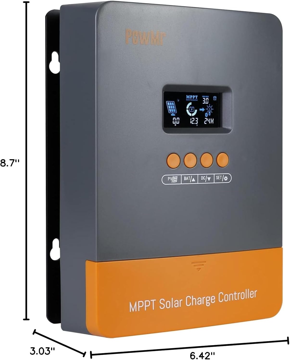
Figure 4.2: Product Dimensions
5. Setup and Installation
Proper installation is crucial for the safe and efficient operation of your MPPT solar charge controller. Follow these steps carefully.
5.1 Mounting the Controller
- Choose a dry, well-ventilated location, protected from direct sunlight, high temperatures, and moisture.
- Ensure there is sufficient clearance around the controller for proper heat dissipation.
- Mount the controller vertically on a non-flammable surface using appropriate fasteners through the mounting holes.
5.2 Wiring Connections
Connect the components in the following order to ensure safety and proper functionality:
- Connect the Battery: Connect the battery to the controller's battery terminals. Ensure correct polarity (positive to positive, negative to negative). The controller will automatically detect the battery voltage.
- Connect the Solar Array: Connect the solar panels to the controller's PV input terminals. Ensure correct polarity. Do not exceed the maximum open-circuit voltage (160VDC) or maximum input power for your system voltage.
- Connect the Load (Optional): If using the load output, connect your DC loads to the controller's load terminals. Ensure correct polarity.
Warning: Always connect the battery first and disconnect the solar array first when disassembling the system.
6. Operating Instructions
6.1 LCD Display and Buttons
The controller features an LCD display that shows various system parameters and four buttons for navigation and settings adjustment.

Figure 6.1: Controller Display and Buttons
- PV/Grid Button: Used to view solar panel parameters.
- BAT/Up Button: Used to view battery parameters and navigate up in menus.
- DC/Down Button: Used to view DC load parameters and navigate down in menus.
- SET/Enter Button: Used to enter settings mode, confirm selections, and save changes.
6.2 Battery Type Settings
The controller is compatible with various battery types. Pre-set charging parameters are available, and you can also customize settings.

Figure 6.2: Applicable Battery Types
To select or customize battery type:
- Press the SET button to enter the settings menu.
- Navigate using the BAT/Up and DC/Down buttons to find the battery type setting.
- Press SET to select, then use BAT/Up and DC/Down to choose the desired battery type (e.g., SEL for Sealed, GEL for Gel, FLD for Flooded, L04-L16 for Lithium, USE for User-Defined).
- Press SET again to confirm and save the setting.
7. Parallel Operation
The PowMr 60A MPPT Solar Charge Controller supports parallel connection of up to 12 units to expand system capacity, power output, and reliability. This setup also improves maintenance flexibility and efficiency.

Figure 7.1: Parallel Operation Schematic
Important Notes for Parallel Operation:
- In parallel operation, communication between controllers is achieved through communication lines.
- Each controller must be connected to a separate solar array.
- Parallel controllers are connected to the same battery bank.
- A one-click factory reset option is available for convenience in parallel setups.
8. Maintenance
Regular maintenance ensures the longevity and optimal performance of your solar charge controller.
- Cleaning: Periodically clean the controller's exterior with a dry cloth. Ensure ventilation openings are free from dust and debris.
- Connections: Check all wiring connections regularly for tightness and corrosion. Loose connections can cause overheating and damage.
- Environment: Ensure the installation environment remains within the specified operating temperature and humidity ranges.
- Battery Health: Monitor your battery's health and voltage regularly. Ensure it is compatible with the controller's settings.
9. Troubleshooting
This section provides guidance for common issues. For more detailed troubleshooting or persistent problems, refer to the comprehensive troubleshooting list provided with the product or contact customer support.
| Problem | Possible Cause | Solution |
|---|---|---|
| Controller not powering on | Battery not connected or low voltage; reverse polarity. | Check battery connections and voltage. Ensure correct polarity. |
| No charging from solar panels | Solar panels not connected; low solar input; reverse polarity; PV over-voltage. | Check PV connections and polarity. Verify solar input voltage is within range. |
| Load output not working | Load overcurrent; short circuit; load not enabled. | Check load connections and current draw. Remove short circuits. Enable load via settings. |
| Incorrect battery voltage reading | Loose battery connection; incorrect battery type setting. | Tighten battery terminals. Verify battery type setting matches your battery. |
10. Warranty and Support
PowMr is committed to providing high-quality products and excellent customer service. For any questions, technical assistance, or warranty claims, please contact PowMr customer support.
You can find more information and support resources on the official PowMr store:
Visit the PowMr Store on Amazon
Please have your product model (B-POW-M60-ULTRA) and purchase information ready when contacting support for faster service.