ATUUKOPC SU600 Series (1.5KW 380V 3-3PH B)
ATUUKOPC Variable Frequency Drive User Manual
Model: 1.5KW 380V 3-3PH B (SU600 Series)
1. Introduction
This manual provides detailed instructions for the installation, operation, and maintenance of the ATUUKOPC Variable Frequency Drive (VFD). This device is designed to control the speed of AC motors by varying the frequency and voltage supplied to the motor. Please read this manual thoroughly before operating the device to ensure safe and efficient use.
The ATUUKOPC VFD is suitable for a wide range of industrial and commercial applications requiring precise motor speed control, such as pumps, fans, conveyors, and machine tools.
2. Safety Information
WARNING: Improper installation or operation may result in serious injury or death. Always follow safety precautions.
- Ensure all power is disconnected before installation, wiring, or maintenance.
- Only qualified personnel should install, operate, and maintain this equipment.
- Do not touch electrical components immediately after power-off; residual voltage may be present. Wait at least 5 minutes for capacitors to discharge.
- Ensure proper grounding of the VFD and the motor.
- Protect the VFD from moisture, dust, corrosive gases, and direct sunlight.
- Do not operate the VFD with damaged cables or components.
Observe all local and national electrical codes and regulations.
3. Product Overview
The ATUUKOPC Variable Frequency Drive features a robust design with an intuitive control panel for easy operation and monitoring.
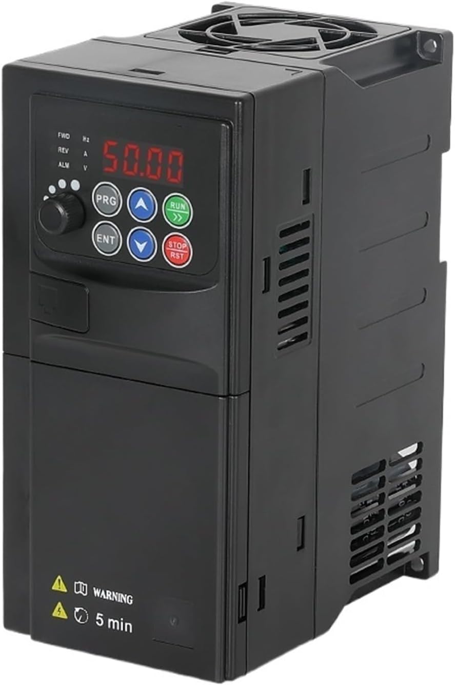
Figure 3.1: Front view of the ATUUKOPC Variable Frequency Drive, showing the digital display and control buttons.
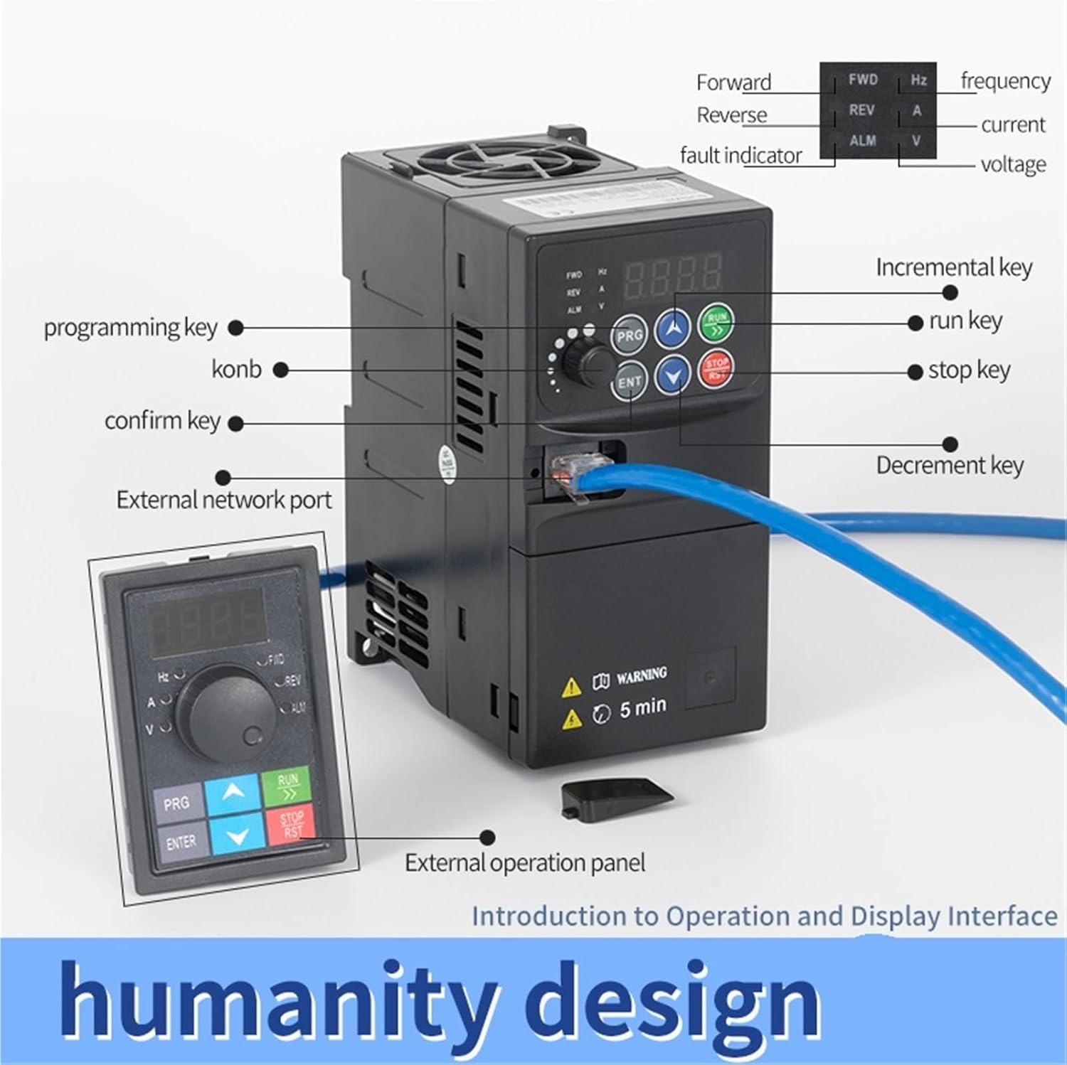
Figure 3.2: Detailed view of the VFD's control panel, highlighting the display, programming key, run key, stop key, increment/decrement keys, confirm key, and external network port. An external operation panel is also shown connected.
3.1 Main Components and Controls
- Digital Display: Shows output frequency, current, voltage, and alarm codes.
- PRG (Program) Key: Enters/exits parameter setting mode.
- ENT (Enter) Key: Confirms parameter settings.
- RUN Key: Starts motor operation.
- STOP/RST Key: Stops motor operation or resets alarms.
- Up/Down Arrows: Adjust frequency, navigate parameters, or change values.
- External Network Port: For remote control or monitoring.

Figure 3.3: Internal view of the VFD, illustrating the main board components. The main board material is characterized as waterproof, moisture-proof, and mildew-proof.
4. Specifications
The following table details the technical specifications for the 1.5KW 380V 3-3PH B model of the ATUUKOPC Variable Frequency Drive.
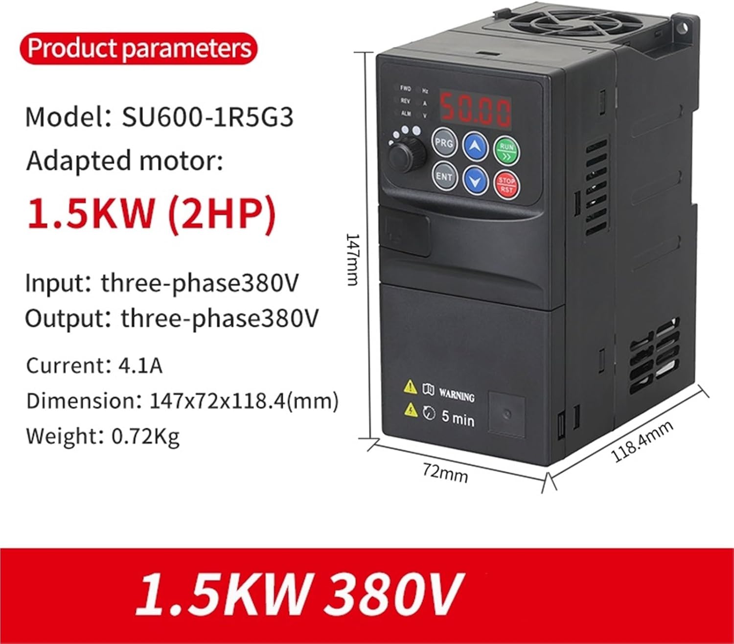
Figure 4.1: Product parameters and dimensions for the 1.5KW 380V VFD, showing model SU600-1R5G3, adapted motor 1.5KW (2HP), input/output three-phase 380V, current 4.1A, dimension 147x72x118.4mm, and weight 0.72Kg.
| Parameter | Value (1.5KW 380V 3-3PH B) |
|---|---|
| Model Number | SU600-1R5G3 |
| Adapted Motor Power | 1.5KW (2HP) |
| Input Voltage | Three-phase 380V |
| Output Voltage | Three-phase 380V |
| Output Current | 4.1A |
| Output Frequency Range | 50-400Hz |
| Dimensions (L*W*H) | 147mm * 72mm * 118.4mm |
| Weight | 0.72Kg |
| Operating Temperature | -10°C to 40°C |
| Humidity | Less than 90% RH (non-condensing) |
5. Setup and Wiring
Proper wiring is critical for the safe and correct operation of the VFD. Refer to the wiring diagram below and ensure all connections are secure.
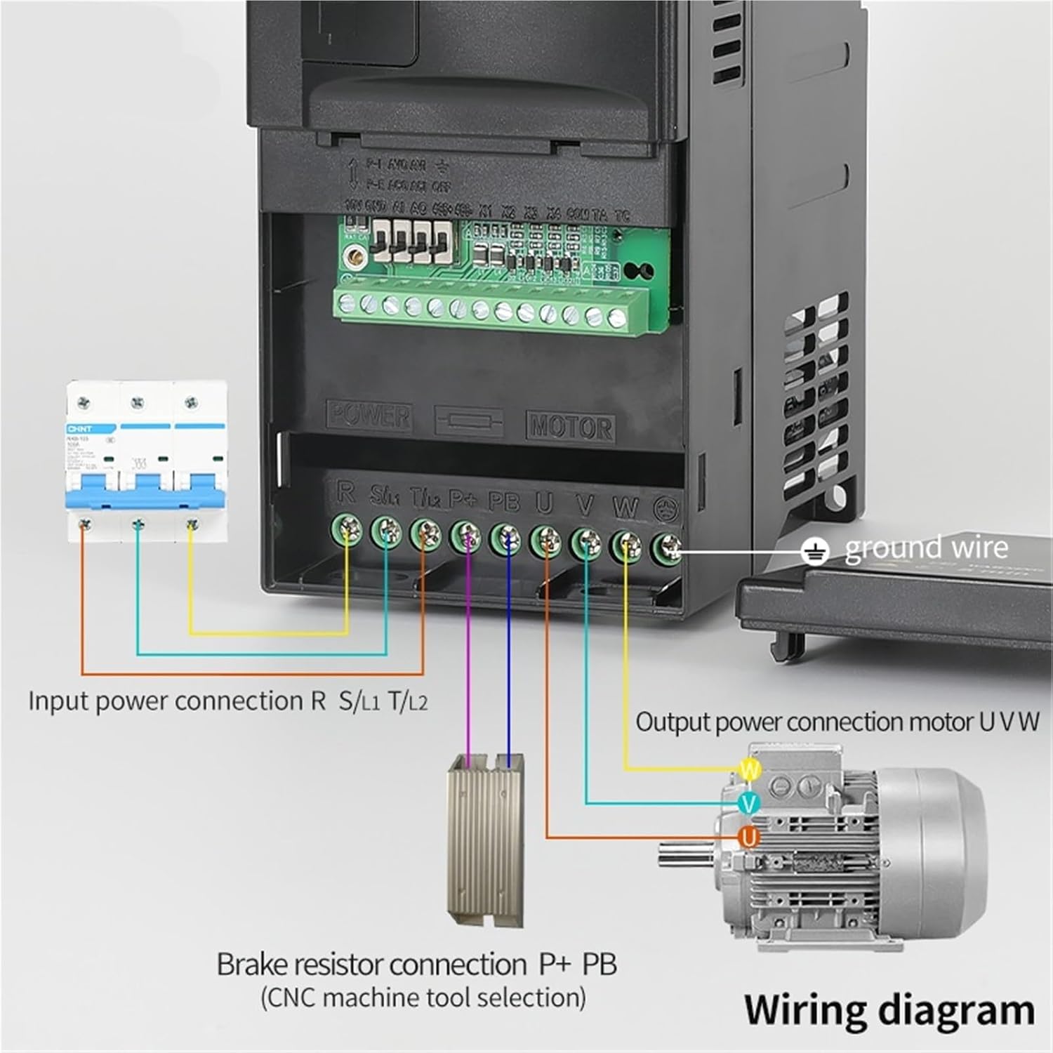
Figure 5.1: Wiring diagram for the VFD. It illustrates the input power connection (R, S/L1, T/L2), output power connection to the motor (U, V, W), and optional brake resistor connection (P+, PB). A ground wire connection is also shown.
5.1 Wiring Connections
- Input Power (R, S/L1, T/L2): Connect the three-phase 380V AC power supply to these terminals. Ensure correct phase sequence.
- Output Power (U, V, W): Connect these terminals directly to the three-phase motor. Do not connect any capacitors or surge suppressors between the VFD and the motor.
- Ground (GND): Connect the VFD's ground terminal to a reliable earth ground. This is essential for safety.
- Brake Resistor (P+, PB): If required for applications with frequent braking or high inertia loads, connect an external brake resistor to these terminals. (CNC machine tool selection)
- Control Terminals: Refer to the detailed wiring diagram in the full manual for connections related to external control signals (e.g., start/stop, speed reference, fault output).
After wiring, double-check all connections for tightness and correctness before applying power.
6. Operating Instructions
This section outlines the basic steps for operating the ATUUKOPC VFD using its control panel.
6.1 Initial Power-Up
- Ensure all wiring is complete and secure.
- Apply power to the VFD. The digital display should light up.
- The display will typically show the default output frequency (e.g., 50.00 Hz).
6.2 Basic Operation (Panel Control)
- Setting Frequency:
- Press the PRG key to enter parameter setting mode.
- Navigate to the frequency setting parameter (e.g., F0.01) using the Up/Down arrow keys.
- Press ENT to edit the value.
- Use the Up/Down arrow keys to adjust the desired output frequency.
- Press ENT to confirm the new frequency.
- Press PRG to exit parameter mode.
- Starting the Motor: Press the RUN key. The motor should start and accelerate to the set frequency.
- Stopping the Motor: Press the STOP/RST key. The motor will decelerate and stop.
6.3 Advanced Parameter Settings
The VFD has numerous parameters for fine-tuning performance, including acceleration/deceleration times, motor parameters, control modes (V/F, vector control), and protection settings. Refer to the comprehensive parameter list in the full product manual for detailed descriptions and adjustment procedures.
- Acceleration/Deceleration Time: Adjust these to control how quickly the motor speeds up or slows down.
- Motor Parameters: Input your motor's rated voltage, current, frequency, and poles for optimal performance.
- Control Mode: Select between V/F control (constant torque) or sensorless vector control (higher performance).
7. Maintenance
Regular maintenance ensures the longevity and reliable operation of your ATUUKOPC VFD.
- Cleaning: Periodically clean the VFD's exterior with a soft, dry cloth. Do not use liquid cleaners or solvents. Ensure ventilation openings are free from dust and debris.
- Fan Inspection: Check the cooling fan for proper operation and cleanliness. A clogged fan can lead to overheating.
- Terminal Tightness: Annually check all wiring terminals for tightness. Loose connections can cause overheating and damage.
- Environmental Check: Ensure the operating environment remains within specified temperature and humidity ranges.
- Capacitor Life: Electrolytic capacitors have a finite lifespan. If the VFD is used continuously for many years, consider professional inspection or replacement.
Always disconnect power and wait for residual voltage to dissipate before performing any maintenance.
8. Troubleshooting
This section provides solutions for common issues you might encounter with your VFD. For more complex problems, contact technical support.
| Problem | Possible Cause | Solution |
|---|---|---|
| VFD does not power on. | No input power; Blown fuse; Internal fault. | Check power supply; Check fuses; Contact support if power is present but unit is dead. |
| Motor does not run. | Incorrect wiring; Motor parameters not set; VFD in fault state; Stop command active. | Verify wiring (U, V, W); Set motor parameters correctly; Check for fault codes and clear; Ensure RUN command is active. |
| Overcurrent (OC) fault. | Motor overload; Short circuit in motor/cables; Rapid acceleration/deceleration. | Reduce load; Check motor and cables for shorts; Increase acceleration/deceleration times. |
| Overvoltage (OV) fault. | Rapid deceleration; High input voltage; Regenerative load. | Increase deceleration time; Check input voltage; Install brake resistor if needed. |
| Overheat (OH) fault. | Poor ventilation; High ambient temperature; Clogged fan. | Ensure adequate ventilation; Clean fan and heatsink; Reduce ambient temperature. |
If a fault persists after attempting the suggested solutions, record the fault code displayed on the VFD and contact customer support.
9. Warranty and Support
ATUUKOPC products are designed for reliability and performance. For specific warranty terms and conditions, please refer to the documentation provided with your purchase or visit the official ATUUKOPC website.
Extended protection plans may be available for purchase to provide additional coverage beyond the standard warranty period. Please check with your retailer for details on available protection plans.
9.1 Customer Support
For technical assistance, troubleshooting, or inquiries regarding your ATUUKOPC Variable Frequency Drive, please contact our customer support team:
- Email: [Manufacturer's Support Email - Placeholder, as not provided]
- Phone: [Manufacturer's Support Phone - Placeholder, as not provided]
- Website: www.atuukopc.com (Example link, actual URL not provided)
When contacting support, please have your product model number (1.5KW 380V 3-3PH B) and purchase date ready.
Ask a question about this manual
Ask about setup, troubleshooting, compatibility, parts, safety, or missing instructions. Manuals+ will review the question and use this page’s manual context to help answer it.