FRPKPNOX QDY30A-B
FRPKPNOX Submersible Liquid Level Transmitter QDY30A-B User Manual
Model: QDY30A-B | Brand: FRPKPNOX
1. Introduction
This manual provides detailed instructions for the installation, operation, and maintenance of the FRPKPNOX Submersible Liquid Level Transmitter, Model QDY30A-B. This device is designed for accurate hydrostatic level measurement in various liquid applications. Please read this manual thoroughly before installation and operation to ensure proper use and optimal performance.
2. Product Overview
The FRPKPNOX QDY30A-B is a high-precision submersible liquid level transmitter. It utilizes a diffused silicon chip core and a 316L diaphragm for reliable and accurate measurements. The robust 304 probe material ensures durability in various liquid environments. This model is available with multiple output signal options and measuring ranges to suit diverse industrial and scientific applications.
2.1 Key Features
- Submersible design for direct liquid immersion.
- High-accuracy diffused silicon chip core.
- Corrosion-resistant 304 probe and 316L diaphragm.
- Multiple output signal options (e.g., 4-20mA, 0-10V, 0-3.3V, 0-5V, 0.5-4.5V, RS485).
- Wide range of measuring depths (e.g., 1-5m, 10m, 15m, 20m, 30m).
- Designed for hydrostatic level measurement.
2.2 Product Components
The level transmitter consists of a sensor probe, a sealed cable, and internal electronics for signal processing. The probe is designed to be submerged in the liquid, while the cable connects it to the power supply and receiving instrument.
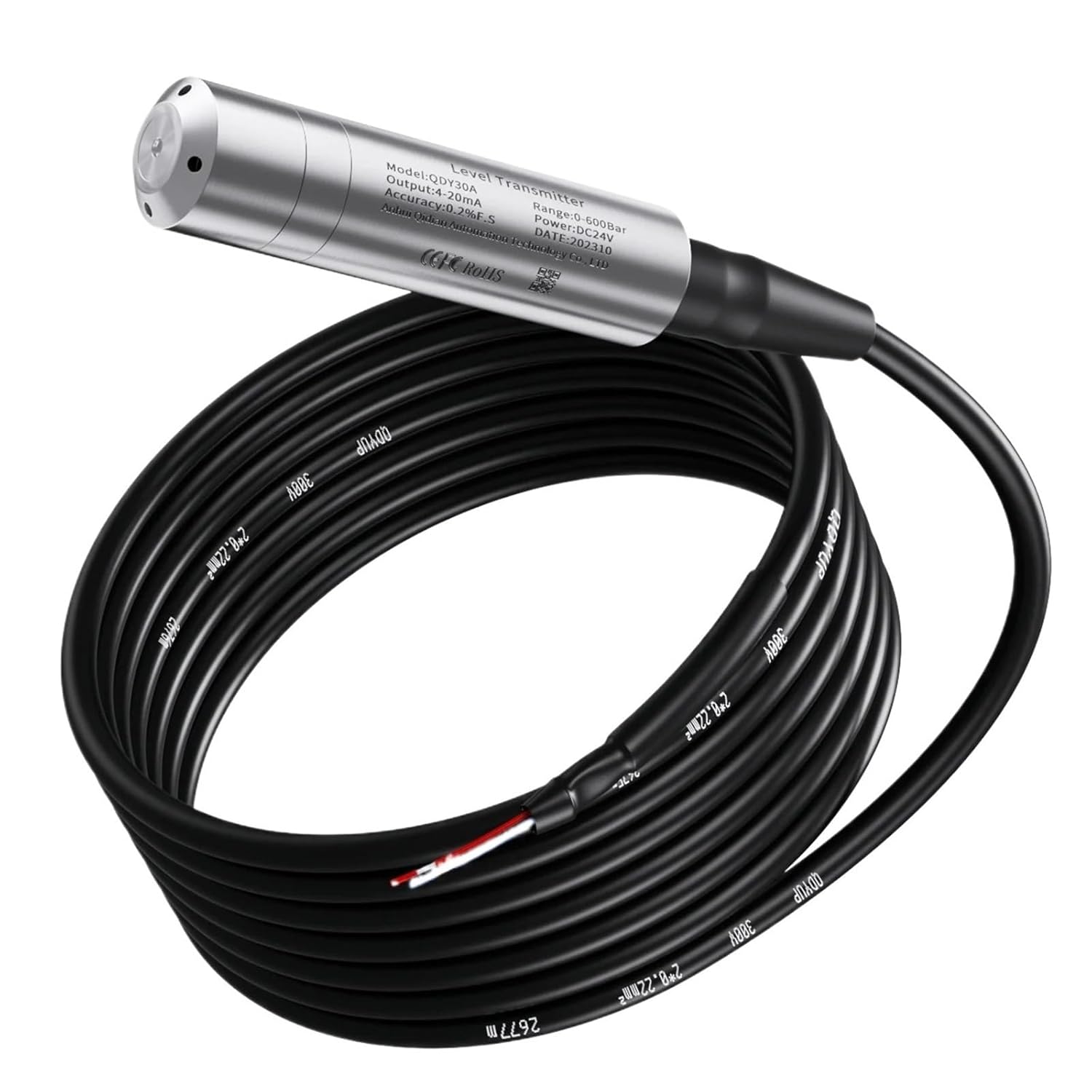
Figure 1: FRPKPNOX Submersible Liquid Level Transmitter with its coiled cable. This image shows the main sensor unit and the attached cable, ready for deployment.

Figure 2: A close-up view of the FRPKPNOX Level Transmitter's body, displaying the model number (QDY30A-B), output signal (4-20mA), accuracy (0.2%F.S), range (0-5M), power (DC24V), and manufacturing date.
3. Specifications
| Parameter | Detail |
|---|---|
| Model Number | QDY30A-B |
| Measuring Range | 1-5M / 10M / 15M (Specific variant: 10M Range) |
| Output Signal | 4-20mA, 0-10V, 1-5V, RS485 (Specific variant: 0-3.3V Output) |
| Material (Probe) | 304 Stainless Steel |
| Material (Diaphragm) | 316L Stainless Steel |
| Core Type | Diffused Silicon Chips |
| Power Supply | DC24V |
| Cable Length | 10M (for this specific variant) |
| Accuracy | 0.2% F.S (Full Scale) |
| Package Dimensions | 0.39 x 0.39 x 0.39 inches |
| Item Weight | 1.76 ounces |
4. Setup and Installation
Proper installation is crucial for the accurate and reliable operation of your liquid level transmitter. Follow these steps carefully:
4.1 Safety Precautions
- Ensure the power supply is disconnected before any wiring or installation.
- Verify that the liquid to be measured is compatible with the sensor's materials (304 probe, 316L diaphragm).
- Avoid bending or kinking the cable excessively, as this can damage internal wires.
- Wear appropriate personal protective equipment (PPE) during installation.
4.2 Mounting the Transmitter
- Select Location: Choose a location where the sensor can be fully submerged in the liquid and where the cable can be routed safely to the control unit.
- Secure Cable: Secure the cable at the top of the tank or well using a suitable clamp or bracket. Ensure the sensor hangs freely and vertically in the liquid, away from inlet streams or agitators that could cause turbulence.
- Ventilation: The cable contains a vent tube to equalize atmospheric pressure. Ensure the end of the cable (where the vent tube terminates) is protected from moisture and contaminants. Do not seal the vent tube.
- Submersion Depth: Ensure the sensor is submerged to the desired measurement depth, but not so deep that the cable is under excessive strain.
4.3 Wiring Instructions
The QDY30A-B transmitter requires a DC24V power supply. The wiring configuration depends on the output signal type. Refer to the specific wiring diagram for your model variant (e.g., 0-3.3V output).
- Power Supply: Connect the positive (+) terminal of the DC24V power supply to the designated power input wire of the transmitter. Connect the negative (-) terminal to the common ground.
- Signal Output (0-3.3V Example):
- Connect the signal output wire to the input of your receiving instrument (e.g., PLC, data logger).
- Ensure the receiving instrument's input impedance is compatible with the transmitter's output.
- Shielding: If the cable has a shield, connect it to earth ground at the control panel side only to prevent ground loops.
Note: Always consult the specific wiring diagram provided with your product for precise connections. Incorrect wiring can damage the device.
5. Operating Instructions
Once the FRPKPNOX QDY30A-B transmitter is correctly installed and wired, operation is straightforward:
- Power On: Apply DC24V power to the transmitter.
- Signal Monitoring: Monitor the output signal (e.g., 0-3.3V) on your connected receiving instrument. The output signal will correspond to the measured liquid level.
- Calibration (if necessary): While factory calibrated, minor adjustments may be needed for specific applications. Refer to your receiving instrument's manual for scaling the input signal to actual liquid depth units. For example, a 0-3.3V output for a 10M range means 0V corresponds to 0M depth and 3.3V corresponds to 10M depth.
- Environmental Considerations: Ensure the operating environment (temperature, pressure) remains within the specified limits for the transmitter to maintain accuracy.
6. Maintenance
The FRPKPNOX QDY30A-B is designed for minimal maintenance. However, periodic checks can extend its lifespan and ensure continued accuracy:
- Cleaning: Periodically inspect the sensor probe for buildup of dirt, algae, or other contaminants. Gently clean the probe surface with a soft cloth and mild detergent if necessary. Avoid abrasive materials that could scratch the diaphragm.
- Cable Inspection: Check the cable for any signs of damage, cuts, or wear. Ensure the cable's vent tube opening is clear and protected from moisture.
- Connection Integrity: Verify that all electrical connections are secure and free from corrosion.
- Recalibration: If accuracy drifts over time or after significant environmental changes, recalibration may be required. This typically involves comparing the sensor's reading to a known liquid level and adjusting the scaling in your receiving instrument.
7. Troubleshooting
If you encounter issues with your liquid level transmitter, refer to the following common problems and solutions:
| Problem | Possible Cause | Solution |
|---|---|---|
| No output signal or incorrect reading. |
|
|
| Inaccurate readings. |
|
|
| Intermittent signal. |
|
|
8. Warranty and Support
For warranty information, technical support, or service inquiries regarding your FRPKPNOX Submersible Liquid Level Transmitter, please contact the manufacturer or your authorized distributor. Keep your purchase receipt and product model number (QDY30A-B) readily available when seeking support.
Additional protection plans may be available through your retailer. Please refer to the terms and conditions of any such plans for details.
Related Documents - QDY30A-B
 |
Qidian QDY30A-B Submersible Liquid Level Sensor - Technical Overview and Installation Detailed information on the Qidian QDY30A-B submersible liquid level sensor, featuring IP68 protection, 0.2% accuracy, durable 304 stainless steel construction, and 4-20mA output. Includes installation guide and precautions. |
 |
Thermocouple Temperature Transmitter - Vadias Product Specifications and Installation Guide Detailed technical specifications, product overview, wiring diagrams, and installation precautions for the Vadias Thermocouple Temperature Transmitter. This device converts thermocouple signals into standard current and voltage outputs for industrial control systems. |
 |
TREEDIX USB Cable Tester Manual: Features, Pinouts, and Usage Guide Comprehensive guide to the TREEDIX USB Cable Tester, detailing its USB ports, pinout configurations for various USB types (Type-A, Type-C, Micro-B, Mini-B, Lightning), battery usage, and instructions for testing USB cables based on LED indicators. |
 |
LINDY 10m USB 3.0 A/B Active Cable User Manual User manual for the LINDY 10m USB 3.0 A/B Active Cable, detailing features, specifications, package contents, installation, and operation. Supports USB 3.2/3.1 Gen 1 up to 5Gbps. |
 |
Industrial Pressure Transmitter for Absolute and Relative Pressure Measurement - B+B SENSORS Technical datasheet for B+B SENSORS industrial pressure transmitters, detailing features, specifications, connection diagrams, dimensions, and a comprehensive product range for absolute and relative pressure measurement. |
 |
TSI Link Report Creator A-B Comparison Workbook Guide A comprehensive guide to using the TSI Link Report Creator for performing A-B comparisons of environmental data, covering setup, analysis, and reporting features. |
Ask a question about this manual
Ask about setup, troubleshooting, compatibility, parts, safety, or missing instructions. Manuals+ will review the question and use this page’s manual context to help answer it.