1. Introduction
This manual provides detailed instructions for the safe and effective operation of the BSIDE 02 Pro Digital Transistor Tester. This device is designed for engineers, electronic maintenance professionals, and hobbyists to accurately identify and test various electronic components, including transistors, diodes, capacitors, resistors, and inductors. Its intuitive design and comprehensive analysis capabilities make it an essential tool for component verification and circuit debugging.
2. Safety Information
Always observe the following safety precautions to prevent personal injury and damage to the device or components:
- Ensure the device is powered off before connecting or disconnecting components, especially capacitors.
- Discharge any capacitors before testing to prevent damage to the tester. The device includes a discharge resistor for this purpose.
- Do not attempt to test components that are still connected to a live circuit.
- Use the device only as described in this manual.
- Keep the device away from moisture and extreme temperatures.
3. Product Overview
The BSIDE 02 Pro Digital Transistor Tester is a compact and versatile tool. Familiarize yourself with its main components:

Figure 3.1: The BSIDE 02 Pro Digital Transistor Tester alongside its printed instruction manual.

Figure 3.2: Front view of the tester, highlighting the LCD screen, POWER/TEST buttons, and T1, T2, T3 test sockets for DIP components, along with SMD test pads.
3.1 Key Components
- LCD Screen: Displays test results, component type, pin configuration, and other relevant parameters. Features a backlight for clear visibility in various lighting conditions.
- POWER/TEST Buttons: Used to power on the device and initiate a test cycle.
- DIP Test Sockets (T1, T2, T3): For testing through-hole components.
- SMD Test Pads: Dedicated pads for testing Surface Mount Devices (SMD).
- Discharge Resistor: Integrated resistor for safely discharging capacitors before testing.
4. Setup
4.1 Battery Installation
The BSIDE 02 Pro is powered by a 9V battery. To install or replace the battery:
- Locate the battery compartment on the back of the device.
- Slide open the battery cover.
- Connect a 9V battery to the battery clip, ensuring correct polarity.
- Place the battery into the compartment and close the cover securely.

Figure 4.1: Rear view of the tester showing the open battery compartment for 9V battery installation.
4.2 Powering On
Press either of the "POWER/TEST" buttons to turn on the device. The LCD screen will illuminate and display "Bat. X.XV OK Testing..." indicating a battery check and self-test.
5. Operating Instructions
The BSIDE 02 Pro features a one-key operation for quick and efficient testing.
5.1 Basic Component Testing
- Prepare the Component: Ensure the component is not connected to any live circuit and, if it's a capacitor, discharge it using the integrated discharge resistor or an external method.
- Connect the Component:
- For DIP (through-hole) components, insert the leads into the T1, T2, T3 sockets. The tester automatically detects the pin configuration.
- For SMD components, place the component onto the designated SMD test pads.
- Initiate Test: Press the "POWER/TEST" button. The device will automatically identify the component type and measure its parameters.
- Read Results: The LCD screen will display the component type (e.g., NPN transistor, resistor, capacitor), its pinout, and measured values such as resistance, capacitance, inductance, forward voltage drop, HFE, gate threshold voltage, and gate capacitance.
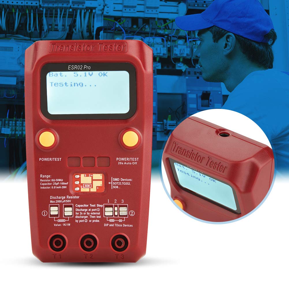
Figure 5.1: The tester actively performing a measurement, with the LCD screen showing "Bat. 5.1V OK Testing..."

Figure 5.2: A detailed view of the tester's screen during operation, showing the battery status and "Testing..." prompt.
5.2 Automatic Component Detection
The tester automatically identifies a wide range of components, including:
- NPN and PNP bipolar transistors
- N-channel and P-channel MOSFETs
- Diodes (including protection diodes)
- Thyristors
- Resistors (0Ω-50MΩ range)
- Capacitors (25pF-100mF range)
- Inductors (0.01mH-20H range)
5.3 Comprehensive Analysis
Beyond basic identification, the BSIDE 02 Pro provides detailed analysis:
- Transistor emitter forward bias voltage
- MOSFET protection diode detection
- Amplification factor (HFE) reference for transistors
- MOSFET gate threshold voltage
- MOSFET gate capacitance
6. Calibration
The device includes a calibration feature to ensure precise and reliable results. Refer to the on-screen prompts or the full printed manual for detailed calibration steps if required. Typically, calibration involves shorting the test probes and following the instructions displayed on the LCD.
7. Maintenance
- Cleaning: Use a soft, dry cloth to clean the device. Do not use abrasive cleaners or solvents.
- Storage: Store the tester in a cool, dry place away from direct sunlight. Remove the battery if the device will not be used for an extended period to prevent leakage.
- Battery Replacement: Replace the 9V battery when the low battery indicator appears on the screen or if the device fails to power on.
8. Troubleshooting
- Device does not power on: Check if the 9V battery is correctly installed and has sufficient charge. Replace the battery if necessary.
- Inaccurate readings: Ensure components are properly connected to the test sockets/pads. Perform a calibration if readings are consistently off.
- "Unknown component" or error message: Verify the component is within the tester's measurable range. Ensure capacitors are fully discharged before testing.
- Screen is dim: The backlight may be off or the battery may be low. Replace the battery.
9. Specifications
| Feature | Specification |
|---|---|
| Resistor Range | 0Ω - 50MΩ |
| Capacitor Range | 25pF - 100mF |
| Inductor Range | 0.01mH - 20H |
| Display | LCD with Backlight |
| Power Source | 9V Battery (not included) |
| Automatic Shutdown | Yes (20s auto-off) |
| Package Dimensions | 7.09 x 4.33 x 2.36 inches |
| Item Weight | 7.87 ounces |
| Model Number | plplaaoonizwaqorxm |
| Manufacturer | plplaaoo |

Figure 9.1: The back of the tester features a printed table of typical ESR values for electrolytic capacitors, useful for quick reference.
10. Warranty and Support
For warranty information and technical support, please refer to the contact details provided with your purchase or visit the official plplaaoo website. Keep your proof of purchase for any warranty claims.