1. Introduction
This manual provides detailed instructions for the installation, operation, and maintenance of your Thermaltake AX500 Snow TG Full Tower Chassis. Please read this manual thoroughly before beginning your system build to ensure proper assembly and optimal performance. The AX500 Snow TG is designed to accommodate a wide range of components, from standard ATX systems to high-performance workstations and gaming rigs, supporting SSI-CEB and SSI-EEB server boards.

Figure 1.1: Overview of the Thermaltake AX500 Snow Full Tower Chassis, highlighting its design for high-performance workstations, gaming setups, and AI computing.
2. Package Contents
Verify that all components are present in the package. If any items are missing or damaged, please contact your retailer or Thermaltake support.
- Thermaltake AX500 Snow TG Full Tower Chassis
- Four (4) 140mm CT Fans (pre-installed)
- Accessory Box (screws, standoffs, cable ties, GPU brace with 2 adjustable supports)
- User Manual (this document)

Figure 2.1: The Thermaltake AX500 Snow TG Full Tower Chassis as it appears out of the box, showcasing its spacious interior and perforated front panel.
3. Specifications
The following table outlines the technical specifications of the Thermaltake AX500 Snow TG Full Tower Chassis.
| Feature | Specification |
|---|---|
| Model Name | AX500 TG Snow |
| Model Number | CA-11D-00F6WN-00 |
| Case Type | Full Tower |
| Dimensions (L x W x H) | 21.57 x 9.76 x 21.65 inches (550 x 248 x 550 mm) |
| Weight | 29.3 pounds (13.3 kg) |
| Material | SPCC Steel, Tempered Glass, Plastic |
| Motherboard Compatibility | SSI-EEB, SSI-CEB, E-ATX, ATX, Micro ATX, Mini ITX |
| Expansion Slots | 8 |
| Drive Bays | 5 x 3.5" HDDs or 6 x 2.5" SSDs (via two drive cages and one drive plate) |
| I/O Ports | 1 x USB 3.2 Gen 2 Type-C, 2 x USB 3.0 Type-A, 1 x HD Audio, Reset Button, HDD LED |
| CPU Cooler Clearance | Up to 185mm |
| GPU Length Clearance | Up to 460mm |
| PSU Length Clearance | Up to 200mm |
| Fan Support (Max) | Front: 3x140mm or 4x120mm; Top: 3x140mm or 3x120mm; Rear: 1x140mm or 1x120mm; Right (M/B Side): 2x140mm or 3x120mm; Power Cover: 3x120mm |
| Radiator Support (Max) | Front: 420mm or 360mm; Top: 420mm or 360mm; Rear: 140mm or 120mm |

Figure 3.1: Diagram illustrating the key dimensions, component clearances, I/O ports, and storage capabilities of the AX500 Snow TG chassis.
4. Chassis Features Overview
The AX500 Snow TG chassis is engineered with several features to facilitate a high-performance build and ease of use.
4.1. Cooling System
The chassis supports extensive cooling configurations, including multiple fans and large radiators. Four 140mm CT fans are pre-installed to provide immediate cooling performance.

Figure 4.1: The AX500 Snow TG chassis showcasing the four pre-installed 140mm CT fans, designed for effective cooling.

Figure 4.2: Diagrams illustrating various fan and radiator placement options within the chassis for superior cooling.
4.2. Storage Options
The chassis offers flexible storage solutions with dedicated drive cages and a drive plate.

Figure 4.3: Diagram detailing the placement and capacity of the drive cages (up to 4 x 3.5" HDDs or 4 x 2.5" SSDs) and the drive plate (1 x 3.5" HDD or 2 x 2.5" SSDs).
4.3. GPU Holder
A built-in GPU holder is included to provide additional support for graphics cards, preventing sagging, especially with multiple or heavy GPUs.

Figure 4.4: Image highlighting the integrated GPU holder within the AX500 Snow TG chassis, designed to support graphics cards.
4.4. Hidden Connector Motherboard Support
The motherboard tray features cutouts specifically designed to support hidden connector ATX and Micro-ATX motherboards, such as ASUS BTF, MSI PROJECT ZERO, and GIGABYTE PROJECT STEALTH series, for a cleaner build aesthetic.

Figure 4.5: Diagram showing the motherboard tray cutouts for hidden connector motherboards, facilitating cable management.
4.5. Front I/O Ports
The top panel provides convenient access to essential connectivity.

Figure 4.6: Close-up view of the top I/O ports, including USB Type-C, USB 3.0, HD Audio, Reset Button, and HDD LED.
5. Installation Guide
Follow these steps to install your components into the Thermaltake AX500 Snow TG chassis.
5.1. Preparing the Chassis
- Place the chassis on a stable, flat surface.
- Remove the side panels by unscrewing the thumbscrews at the rear and sliding the panels off.
- Identify the accessory box containing screws, standoffs, and other small parts.
5.2. Motherboard Installation
- Install the appropriate standoffs onto the motherboard tray according to your motherboard's form factor (SSI-EEB, SSI-CEB, E-ATX, ATX, Micro ATX, Mini ITX).
- Carefully place your motherboard onto the standoffs, aligning the screw holes.
- Secure the motherboard with the provided screws.
5.3. Power Supply Installation
- Position the power supply unit (PSU) in the dedicated compartment at the bottom rear of the chassis.
- Ensure the PSU fan faces the bottom ventilation opening for optimal airflow.
- Secure the PSU to the chassis with the provided screws from the rear.
5.4. Storage Device Installation
The chassis supports both 3.5" HDDs and 2.5" SSDs in various configurations.
5.4.1. Drive Cages (Under PSU Cover)
- Slide out the drive trays from the drive cages located under the PSU cover.
- For 3.5" HDDs, flex the tray and align the drive's screw holes with the pins on the tray.
- For 2.5" SSDs, secure the drive to the tray using the provided screws.
- Slide the populated tray back into the drive cage until it clicks into place.
5.4.2. Drive Plate (Behind Motherboard)
- Unscrew and remove the drive plate located behind the motherboard tray.
- Mount one 3.5" HDD or two 2.5" SSDs onto the plate using the appropriate screws.
- Reattach the drive plate to the motherboard tray.
5.5. Expansion Card (GPU) Installation
- Remove the necessary PCIe slot covers from the rear of the chassis.
- Insert your graphics card or other expansion card into the appropriate PCIe slot on the motherboard.
- Secure the card with the provided screws.
- Utilize the included GPU brace to support the graphics card and prevent sagging. Adjust the supports as needed.
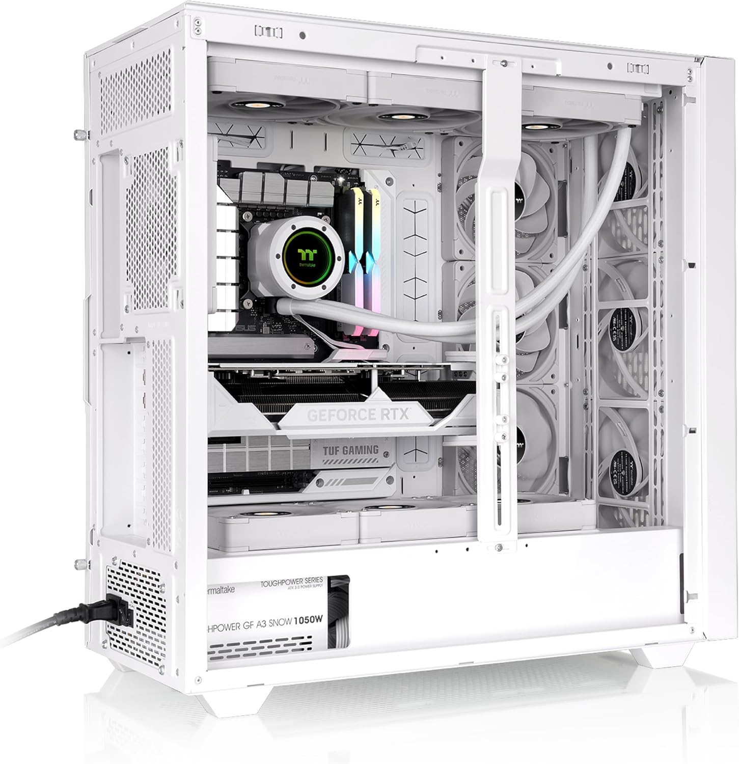
Figure 5.1: An example build showing a graphics card installed and supported by the adjustable GPU brace within the chassis.
5.6. Cooling System Installation (Additional Fans/Radiators)
The chassis supports various fan and radiator configurations. Refer to the specifications for maximum compatibility.
- Identify desired mounting locations for additional fans or radiators (front, top, rear, motherboard side, power cover).
- Secure fans or radiators using the appropriate screws.
- Connect fan cables to your motherboard or a fan controller.

Figure 5.2: A top-down interior view of the chassis with cooling components installed, demonstrating potential fan and radiator placements.
5.7. Cable Management
The AX500 series chassis offers ample cable management clearance and multiple anchor points behind the motherboard tray.
- Route all power and data cables through the designated cutouts and channels behind the motherboard tray.
- Use the included Velcro straps and cable ties to bundle and secure cables, ensuring a tidy and unobstructed airflow path.
- Ensure no cables interfere with fan blades or other moving parts.

Figure 5.3: Diagram illustrating the cable management anchor points and routing channels behind the motherboard tray.

Figure 5.4: Rear interior view of the chassis, demonstrating effective cable routing and management.
5.8. Front Panel Connections
Connect the front panel cables (USB, Audio, Power, Reset, HDD LED) to the corresponding headers on your motherboard. Refer to your motherboard manual for specific header locations.
6. Operating
Once all components are installed and secured, and cables are properly managed, replace the side panels. Your system is now ready for operation. Ensure adequate ventilation around the chassis for optimal cooling performance.

Figure 6.1: The Thermaltake AX500 Snow TG chassis with a complete system build, ready for operation.
7. Maintenance
Regular maintenance helps ensure the longevity and performance of your chassis and components.
- Cleaning: Periodically clean dust filters (if applicable) and interior components using compressed air or a soft brush. Ensure the system is powered off and unplugged before cleaning.
- Cable Management: Occasionally check cable routing to ensure no cables have come loose or are obstructing airflow.
- Fan Inspection: Inspect fans for dust buildup and ensure they are spinning freely.
8. Troubleshooting
This section addresses common issues you might encounter.
- System Not Powering On: Double-check all power connections, including the 24-pin ATX, 8-pin CPU, and GPU power cables. Ensure the PSU switch is in the 'ON' position. Verify front panel power button connection to the motherboard.
- No Display Output: Ensure the graphics card is fully seated in its PCIe slot and all necessary power cables are connected. Check monitor connections.
- Overheating: Verify all fans are operating correctly and are oriented for proper airflow. Ensure CPU cooler is properly installed. Clean dust filters and internal components.
- Excessive Noise: Identify the source of the noise. It could be a loose fan, a vibrating component, or a cable interfering with a fan.
For further assistance, refer to your individual component manuals or contact Thermaltake support.
9. Warranty and Support
Thermaltake products are manufactured to high standards and come with a limited warranty. Please refer to the official Thermaltake website for the most current warranty information and terms specific to your region.
For technical support, product inquiries, or warranty claims, please visit the official Thermaltake support page or contact their customer service department. Keep your proof of purchase for warranty validation.
- Thermaltake Official Website: www.thermaltake.com
- Support: Refer to the 'Support' or 'Contact Us' section on the official website.