1. Introduction
This manual provides detailed instructions for the installation, operation, and maintenance of the HFFFXRCY 5.5KW Hybrid Solar Inverter, model SML-III-3.5KW-WiFi. This device is a pure sine wave inverter with an integrated 100A MPPT solar charge controller, designed to efficiently convert DC power from solar panels and batteries into AC power for various loads. It supports a wide PV input voltage range of 120-500VDC and can operate without a battery, directly supplying power from PV to the load.
2. Safety Information
Important Safety Instructions: Please read all instructions and cautionary markings on the unit and in this manual before installation and operation. Improper installation or use may result in electric shock, fire, or serious injury.
- Qualified Personnel: All electrical installations must be performed by qualified personnel in accordance with local electrical codes and regulations.
- High Voltage: The inverter operates with high voltages. Do not open the unit or attempt repairs unless you are a qualified technician.
- Proper Grounding: Ensure the inverter is properly grounded to prevent electrical hazards.
- Ventilation: Install the inverter in a well-ventilated area to prevent overheating. Do not block ventilation openings.
- Battery Safety: When connecting batteries, ensure correct polarity. Batteries can produce explosive gases; ensure adequate ventilation and avoid sparks or flames near batteries.
- Disconnect Power: Always disconnect all power sources (PV, battery, AC input) before performing any wiring or maintenance.
3. Product Overview
The HFFFXRCY Hybrid Solar Inverter is a versatile power solution. It features a robust design with a clear display for monitoring system status and settings. The unit integrates a powerful MPPT charge controller for efficient solar energy harvesting and a pure sine wave inverter for stable AC output.

Figure 3.1: Front-top view of the HFFFXRCY 5.5KW Hybrid Solar Inverter, showing the blue and black casing with a digital display on top.

Figure 3.2: Composite image showing the front panel with display, top-side perspective, and rear connection panel of the inverter.
Key Features:
- Pure sine wave output for sensitive electronics.
- Integrated 6.0 KW MPPT solar charge controller.
- Maximum charging current of 100A.
- Wide PV input voltage range: 120-500VDC.
- Ability to generate power directly from PV to supply load, even without a battery.
- High PV to AC efficiency.
4. Setup and Installation
Proper installation is crucial for the safe and efficient operation of your hybrid solar inverter. It is highly recommended that installation be performed by a certified electrician or solar professional.
Installation Steps:
- Mounting: Select a suitable location for mounting the inverter. Ensure it is indoors, dry, well-ventilated, and away from direct sunlight, heat sources, and flammable materials. Leave adequate clearance around the unit for airflow.
- Wiring Overview: The inverter requires connections for PV input, battery input, AC input (utility grid or generator), and AC output (to loads). Refer to the system diagram below for a general overview.

Figure 4.1: Diagram illustrating the typical connections for the hybrid solar inverter, including solar panels, generator, utility grid, battery packs, and various home appliances as loads.
- Rear Panel Connections: The rear panel provides all necessary terminals for wiring.
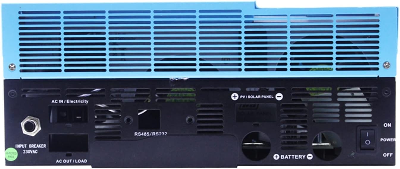
Figure 4.2: Close-up view of the inverter's rear panel, showing terminals for AC IN/Electricity, AC OUT/LOAD, PV/SOLAR PANEL, BATTERY, RS485/RS232 ports, INPUT BREAKER 230VAC, and POWER ON/OFF switch.
- Battery Connection: Connect the battery bank to the BATTERY terminals, ensuring correct polarity (+ to + and - to -). Use appropriate cable gauges.
- PV Array Connection: Connect the solar panel array to the PV/SOLAR PANEL terminals. Ensure the PV input voltage and current are within the inverter's specifications (120-500VDC).
- AC Input Connection: Connect the utility grid or generator to the AC IN/Electricity terminals.
- AC Output Connection: Connect your household loads to the AC OUT/LOAD terminals.
- Grounding: Connect the inverter's chassis ground terminal to a reliable earth ground.
- Initial Power-Up: After all connections are secure and verified, switch on the battery breaker (if applicable), then the PV array breaker, followed by the AC input breaker, and finally the inverter's power switch.
5. Operating Instructions
Once the inverter is properly installed and powered on, the LCD display will show the system status and operational parameters. The inverter will automatically detect input sources and prioritize power flow based on its configured mode.
Display and Buttons: The front panel features an LCD display and several buttons for navigation and setting adjustments. Refer to the product's specific user interface guide for detailed button functions and menu navigation.
Operating Modes:
- Battery Mode: Inverter draws power from batteries to supply loads.
- PV Mode (No Battery): The inverter can directly supply power to loads from the PV array, even without a connected battery. This mode maximizes PV to AC efficiency.
- Utility Mode: When the utility grid is available, it can charge batteries and/or supply power to loads.
- Hybrid Mode: Combines power from PV, battery, and utility/generator to meet load demands and optimize energy usage.
Powering On/Off:
- To Power On: Ensure all input sources (PV, battery, AC) are connected and their respective breakers are closed. Then, switch the inverter's main power switch to the 'ON' position.
- To Power Off: First, disconnect the AC output loads. Then, switch off the inverter's main power switch. Next, open the AC input breaker, followed by the PV array breaker, and finally the battery breaker.
6. Maintenance
Regular maintenance ensures the longevity and optimal performance of your hybrid solar inverter.
- Cleaning: Periodically clean the exterior of the inverter with a dry, soft cloth. Ensure ventilation openings are free from dust and debris. Do not use liquid cleaners.
- Connection Checks: Annually inspect all electrical connections (PV, battery, AC input/output) for tightness and signs of corrosion. Tighten any loose connections.
- Environmental Check: Ensure the installation environment remains dry, clean, and within the specified temperature range.
- Battery Maintenance: If using lead-acid batteries, follow the battery manufacturer's maintenance guidelines, including checking electrolyte levels and terminal cleanliness.
7. Troubleshooting
This section provides guidance for common issues. For complex problems, contact qualified service personnel.
- No Power Output: Check all input power sources (PV, battery, AC grid/generator) and their respective breakers. Ensure the inverter's power switch is ON. Verify battery voltage is within operating range.
- Inverter Overheating: Check for blocked ventilation openings. Ensure the ambient temperature is not too high. Reduce load if necessary.
- Error Codes: If the display shows an error code, consult the specific error code section in the full user manual (if available) or contact technical support with the code displayed.
- Low Battery Voltage Warning: Ensure batteries are adequately charged. Check charging sources (PV, AC input).
- No PV Charging: Verify PV array connections and ensure PV voltage is within the inverter's MPPT range (120-500VDC). Check for shading on solar panels.
8. Specifications
Detailed technical specifications for the HFFFXRCY 5.5KW Hybrid Solar Inverter (SML-III-3.5KW-WiFi).
| Parameter | Value |
|---|---|
| Model | SML-III-3.5KW-WiFi (48V) |
| Maximum Output Power | 5.5KW / 5500W |
| AC Output Voltage | 220V |
| DC Input Voltage | 48VDC |
| MPPT Solar Charge Controller Current | 100A |
| PV Input Voltage Range | 120-500VDC |
| Inverter Type | Pure Sine Wave |
| Item Weight | 50 Grams |
| Assembly Required | No |
| Number of Pieces | 1 |
| Manufacturer | HFFFXRCY |
| Color | Sml-iii-3.5kw-wifi |
PV Module Selection Parameters (from image):
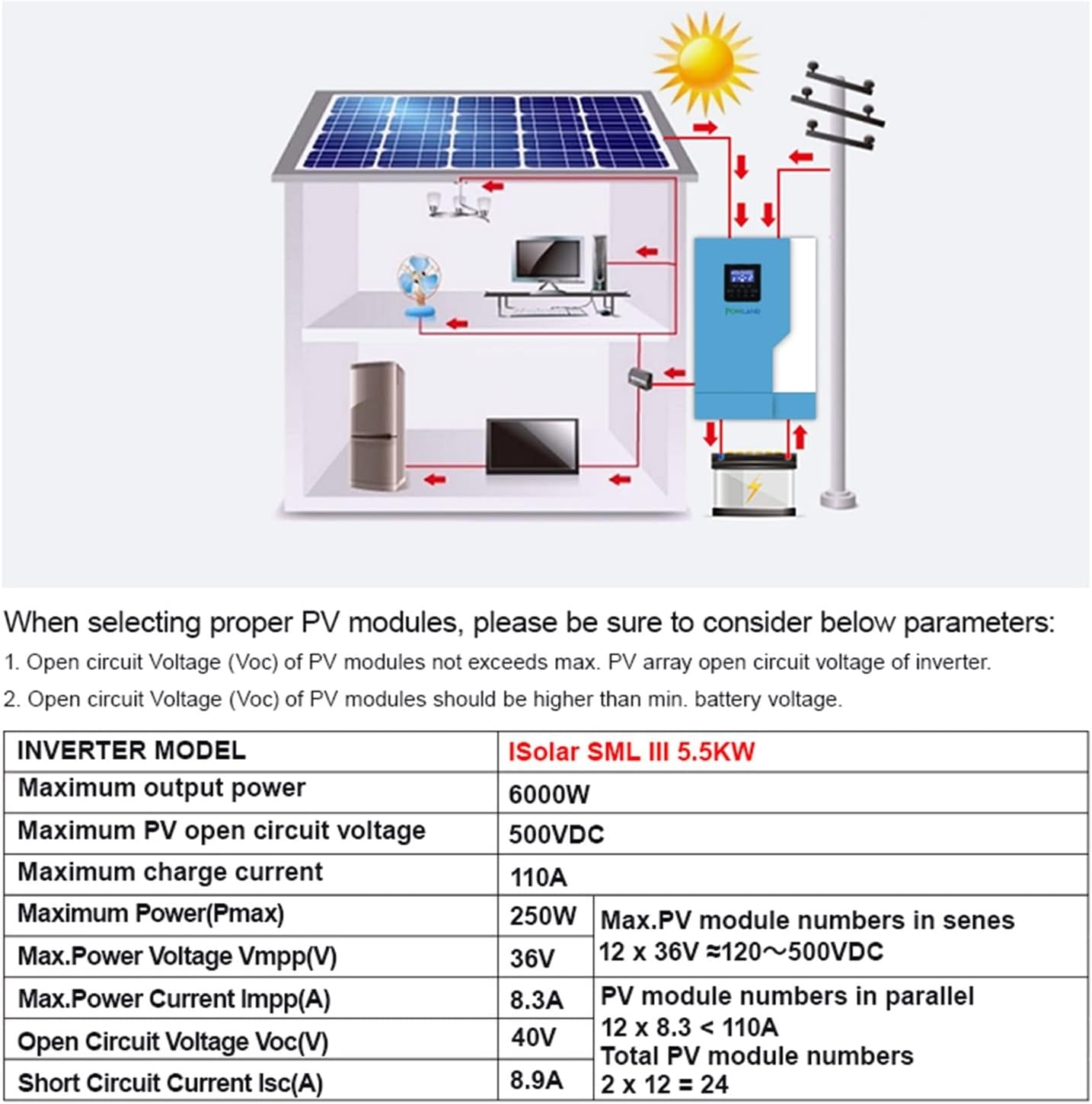
Figure 8.1: Table detailing recommended PV module parameters for the iSolar SML III 5.5KW inverter, including maximum output power, open circuit voltage, charge current, and module numbers for series and parallel connections.
- Maximum output power: 6000W
- Maximum PV open circuit voltage: 500VDC
- Maximum charge current: 110A
- Maximum Power (Pmax): 250W
- Max. Power Voltage Vmpp(V): 36V
- Max. Power Current Impp(A): 8.3A
- Open Circuit Voltage Voc(V): 40V
- Short Circuit Current Isc(A): 8.9A
- Max. PV module numbers in series: 12 x 36V ≈120~500VDC
- PV module numbers in parallel: 12 x 8.3 < 110A
- Total PV module numbers: 2 x 12 = 24
9. Warranty and Support
For warranty information and technical support, please refer to the documentation provided with your purchase or contact the manufacturer directly. Typically, warranty details cover manufacturing defects and specific components for a defined period from the date of purchase. Support channels often include online resources, email, or phone assistance.