1. Introduction
The CIZVVEOC CHLT-63/4P Dual Power Automatic Transfer Switch is designed to automatically switch between a main power supply and a backup power supply. This ensures continuous, safe, and reliable power delivery in environments where uninterrupted power is critical, such as factories and shopping malls. This switch is specifically designed for DIN rail installation within PZ30 distribution boxes.
2. Safety Information
- Professional Installation Required: Installation, maintenance, and repair of this device must be performed by qualified electrical personnel only.
- Power Disconnection: Always disconnect all power sources before installing, servicing, or performing any work on the switch to prevent electric shock.
- Proper Wiring: Ensure all wiring connections are secure and comply with local electrical codes and standards. Incorrect wiring can lead to device malfunction, damage, or electrical hazards.
- Environmental Conditions: Do not expose the switch to excessive moisture, dust, or extreme temperatures outside its specified operating range.
- Inspection: Regularly inspect the switch for any signs of damage, loose connections, or overheating.
3. Product Features
- Silver Contacts: Equipped with silver contacts to significantly enhance conductivity and extend the product's service life.
- PC Shell Construction: The housing is made from safe, flame-retardant PC material, offering excellent insulation, high temperature resistance, and anti-aging properties.
- Fast Switching: Designed for rapid transfer to the backup power supply upon detection of an abnormality in the normal power supply, ensuring uninterrupted operation.
- DIN Rail Type: Specifically engineered for track installation, making it ideal for integration into PZ30 distribution boxes.
- Wide Application: Suitable for various settings requiring continuous power, such as industrial facilities, commercial buildings, and other critical infrastructure.
4. Package Contents
Upon opening the package, verify that all items are present and undamaged:
- 1 x CHLT-63/4P Dual Power Automatic Transfer Switch
- 1 x Instruction Manual (this document)
5. Setup and Installation
Installation should only be performed by a qualified electrician. Ensure all power is disconnected before proceeding.
5.1 Mounting
The CHLT-63/4P is designed for DIN rail mounting. Securely attach the switch to the DIN rail within your PZ30 distribution box.
5.2 Wiring Connections
Refer to the wiring diagram below for proper connection of the main power, backup power, load output, and control lines. Ensure all connections are tight and correct.

Figure 1: Wiring Diagram. This image illustrates the connection points for the common power input (Main Power A), backup power input (Backup Power B), load output, common control line, and backup power control line. Ensure connections match the diagram for correct operation.
Main Power (A): Connect your primary power source to the 'Main Power A' terminals.
Backup Power (B): Connect your secondary or backup power source to the 'Backup Power B' terminals.
Load Output: Connect the devices or circuits to be powered to the 'Load output' terminals.
Control Lines: Connect the common control line and backup power control line as indicated in the diagram for automatic operation.

Figure 2: Product Overview. A general view of the CHLT-63/4P Automatic Transfer Switch, showing the main power input (R, S, T, N), backup power input, and load side connections.
6. Operating Instructions
The CHLT-63/4P switch operates primarily in automatic mode, but also features a manual override.
6.1 Automatic Mode
In automatic mode, the switch continuously monitors the main power supply (Power A). If the main power supply becomes abnormal or fails, the switch will automatically transfer the load to the backup power supply (Power B) without manual intervention. Once the main power supply is restored and stable, the switch will automatically transfer the load back to the main power supply.
6.2 Manual Override
The switch includes a manual selector (often a red button or lever labeled 'Manual' or 'Auto'). To manually switch between power sources, ensure the system is in a safe state and follow the specific instructions on the device or consult a qualified electrician. Typically, this involves moving the selector from 'Auto' to 'Manual' and then physically switching the power source using the lever.

Figure 3: Front View. This image shows the front of the transfer switch, including the manual/auto selector switch and indicators for Main Power (A) and Backup Power (B).
7. Maintenance
Regular maintenance helps ensure the longevity and reliable operation of your automatic transfer switch.
- Visual Inspection: Periodically inspect the switch for any visible damage, discoloration, or signs of overheating.
- Connection Check: Ensure all terminal connections remain tight. Loose connections can cause resistance, heat buildup, and potential failure.
- Cleaning: Keep the switch free from dust and debris. Use a dry, soft cloth for cleaning. Do not use liquid cleaners.
- Functional Test: If safe to do so and with proper precautions, periodically test the automatic transfer function by simulating a main power failure.
8. Troubleshooting
If you encounter issues with your automatic transfer switch, consider the following common troubleshooting steps:
- No Power Transfer:
- Verify both main and backup power sources are active and stable.
- Check all wiring connections for tightness and correctness according to the diagram.
- Ensure the switch is in 'Auto' mode if automatic transfer is desired.
- Intermittent Operation:
- Inspect for loose connections or damaged wiring.
- Check for stable voltage from both power sources. Fluctuations can cause erratic switching.
- Overheating:
- Ensure the switch is not overloaded beyond its rated current.
- Check for proper ventilation around the switch.
- Verify all connections are tight to prevent resistance heating.
If problems persist after attempting these steps, contact a qualified electrician or the manufacturer for assistance.
9. Specifications
The following are the technical specifications for the CHLT-63/4P Dual Power Automatic Transfer Switch:
| Parameter | Value |
|---|---|
| Model | CHLT-63/4P |
| Insulation Voltage | AC690V |
| Rated Voltage | AC400V |
| Coil Voltage | 220VAC |
| Level | PC level |
| Specifications | 4P |
| Electrical Life | 2000 times |
| Mechanical Life | 5000 times |
| Rated Short Circuit Current | 50kA |
| Fuse | RT16 00 63A |
| Rated Impulse Withstand Voltage | 8kV |
| Control Circuit Rated Voltage | AC220V (85% Us - 110% Us) |
| Auxiliary Circuit | 2 relays, each with two sets of contacts |
| Material | PC, Silver |
| Item Weight | 1.76 ounces |
| Dimensions (L x W x H) | Approx. 141mm x 104mm (refer to Figure 4) |
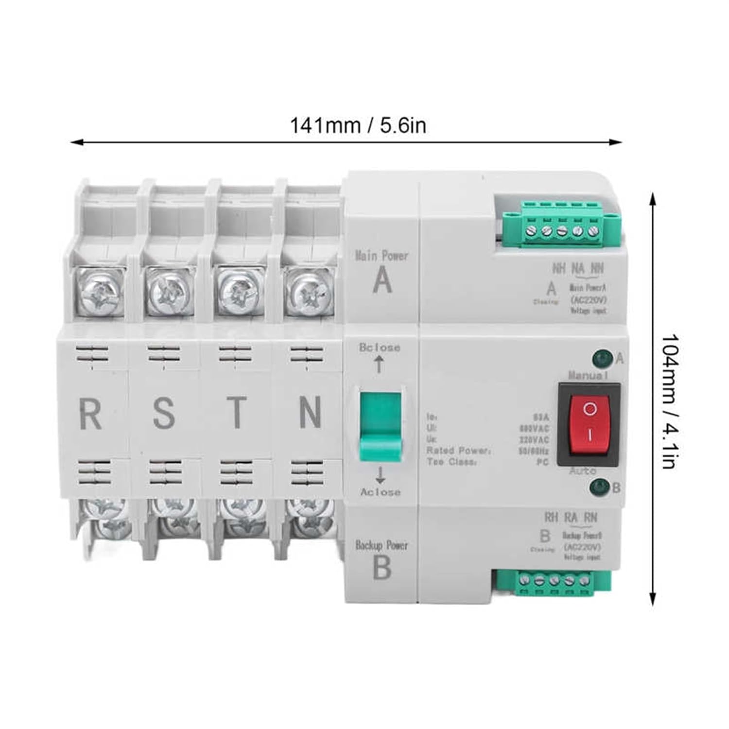
Figure 4: Product Dimensions. This image shows the approximate length (141mm / 5.6in) and height (104mm / 4.1in) of the transfer switch.

Figure 5: Top View. A view from the top of the transfer switch, showing the terminal layout and the manual selector mechanism.

Figure 6: Side View. A side view of the transfer switch, displaying a production process label.
10. Warranty Information
Specific warranty details for the CIZVVEOC CHLT-63/4P Dual Power Automatic Transfer Switch are not provided in the product information. Please refer to your purchase documentation or contact the retailer for warranty terms and conditions.
11. Customer Support
For technical assistance, troubleshooting beyond this manual, or inquiries regarding your CIZVVEOC CHLT-63/4P Dual Power Automatic Transfer Switch, please contact your point of purchase or the manufacturer directly. Specific customer support contact information was not available in the provided product details.