1. Introduction
This manual provides essential information for the safe and effective installation, operation, and maintenance of the HJCMOONB DZ47NZ-125 DC Miniature Circuit Breaker. This device is designed to protect electrical circuits from damage caused by overcurrent, which can result from an overload or short circuit. Please read this manual thoroughly before installation and use, and retain it for future reference.
2. Safety Instructions
Always adhere to the following safety precautions to prevent personal injury or damage to the equipment:
- Installation and maintenance must be performed by qualified personnel only.
- Ensure the power supply is completely disconnected before performing any work on the circuit breaker or associated wiring.
- Verify that the circuit breaker's specifications (voltage, current, poles) match the requirements of your electrical system.
- Do not operate the circuit breaker if it appears damaged or malfunctions.
- Use appropriate personal protective equipment (PPE) during installation and maintenance.
- Observe all local and national electrical codes and regulations.
3. Product Overview
The HJCMOONB DZ47NZ-125 is a DC Miniature Circuit Breaker (MCB) featuring thermal-magnetic trip technology. It is designed for protection against overload and short-circuit conditions in DC power distribution facilities, such as solar photovoltaic systems. It also serves as a control and isolation switch.
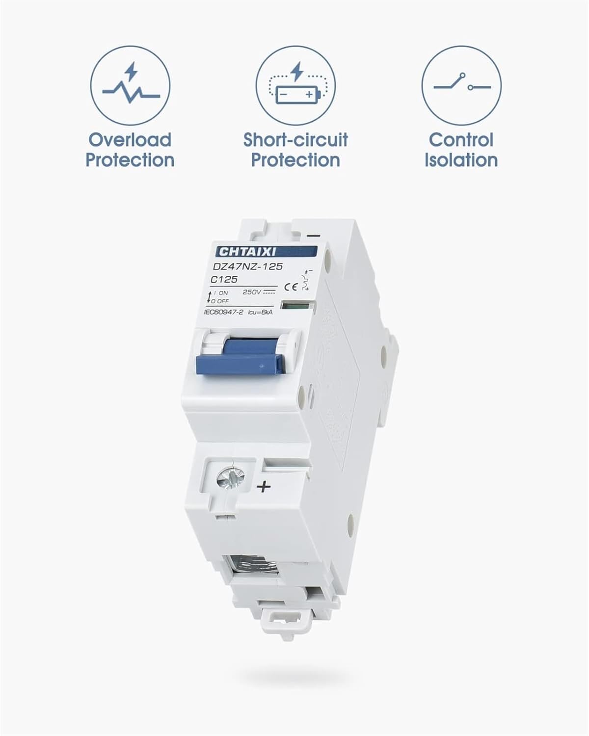
Figure 3.1: Key functions of the DC Miniature Circuit Breaker, including overload protection, short-circuit protection, and control isolation.
Key Features:
- Overload Protection: Prevents damage from excessive current draw.
- Short-circuit Protection: Rapidly disconnects power during a short circuit.
- Control and Isolation: Can be manually switched ON/OFF to isolate circuits.
- Magnetic Arc Extinguishing: Incorporates a magnetic system to assist in extinguishing electrical arcs during disconnection, enhancing safety and device longevity.
- Silver Alloy Contacts: Utilizes silver alloy contacts to reduce heat generation during arcing, improving performance and durability.
- DIN Rail Mount: Designed for easy installation on a standard 35 mm DIN rail.

Figure 3.2: Illustration of the magnetic arc extinguishing mechanism within the circuit breaker.

Figure 3.3: Silver alloy contacts used in the circuit breaker to minimize heat during disconnection.
4. Setup and Installation
The DZ47NZ-125 circuit breaker is designed for mounting on a 35 mm DIN rail. Follow these steps for proper installation:
- Preparation: Ensure all power to the circuit is off. Gather necessary tools (screwdriver, wire strippers, torque wrench).
- Mounting: Hook the top edge of the circuit breaker onto the DIN rail. Press the bottom of the circuit breaker firmly until it clicks into place on the rail.
- Wiring:
- Strip the insulation from the DC power cables to the appropriate length.
- Insert the positive (+) and negative (-) DC cables into the designated terminals on the circuit breaker. Refer to the markings on the device for correct polarity.
- Tighten the terminal screws to a torque of 3.5 N.m (Newton-meters) to ensure a secure connection. Overtightening or undertightening can lead to poor contact and potential hazards.
- Verification: Double-check all connections for tightness and correct polarity. Ensure no bare wires are exposed.

Figure 4.1: Rear view of the circuit breaker, illustrating the DIN rail mounting clip and access points for auxiliaries.
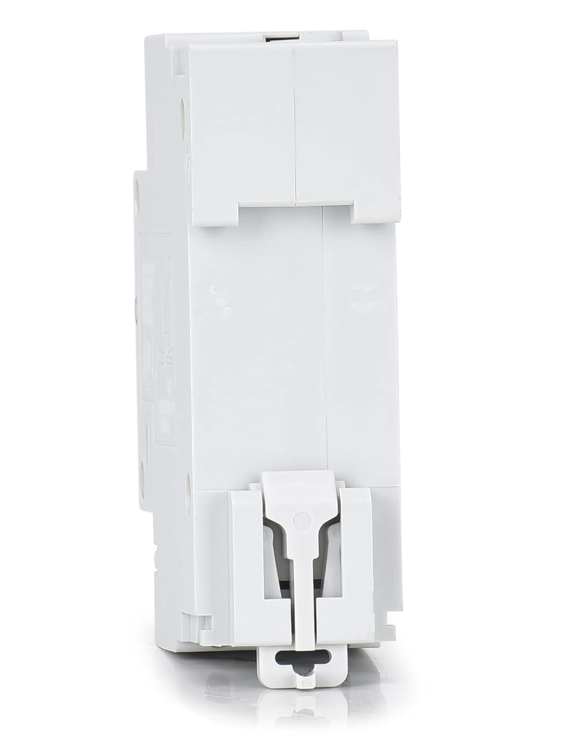
Figure 4.2: Side view of the circuit breaker, showing the DIN rail mounting clip for secure installation.
5. Operating Instructions
The circuit breaker has a simple toggle switch for operation.
- To Turn ON: Push the toggle switch upwards to the 'ON' position.
- To Turn OFF: Push the toggle switch downwards to the 'OFF' position.
- Trip Indication: If an overload or short circuit occurs, the circuit breaker will automatically trip, moving the toggle switch to an intermediate or 'TRIPPED' position (often between ON and OFF). To reset after a trip, first move the switch fully to the 'OFF' position, then push it upwards to 'ON'. Investigate the cause of the trip before resetting.
6. Maintenance
The DZ47NZ-125 circuit breaker requires minimal maintenance. However, periodic checks are recommended:
- Visual Inspection: Regularly inspect the circuit breaker for any signs of physical damage, discoloration, or loose connections.
- Terminal Tightness: Periodically check the tightness of the terminal screws, especially after initial installation and during routine system checks.
- Cleaning: Keep the circuit breaker clean and free from dust and debris. Use a dry, non-abrasive cloth for cleaning. Do not use liquids or solvents.
7. Troubleshooting
If the circuit breaker trips frequently or fails to operate correctly, consider the following:
- Frequent Tripping: This usually indicates an overload or short circuit in the protected circuit. Disconnect loads one by one to identify the faulty device or wiring. Ensure the total current draw does not exceed the circuit breaker's rated current.
- Failure to Reset: If the circuit breaker does not reset after being moved to 'OFF' and then 'ON', there might be a persistent fault (e.g., a direct short circuit) or internal damage to the breaker. Do not force the switch.
- Overheating: If the circuit breaker feels hot to the touch, it could be due to loose connections, an overloaded circuit, or internal damage. Immediately disconnect power and investigate.
- No Power Output: Check if the circuit breaker is in the 'ON' position. Verify input power to the breaker. Inspect wiring for breaks or loose connections.
If issues persist after basic troubleshooting, consult a qualified electrician or contact customer support.
8. Specifications
The following table details the technical specifications for the HJCMOONB DZ47NZ-125 DC Miniature Circuit Breaker:
| Parameter | Specification |
|---|---|
| Main Product Name | DZ47NZ-125 |
| Product Type | DC Miniature Circuit Breaker |
| Rated Operational Voltage | 500 V DC |
| Rated Current [In] | 80 A / 100 A / 125 A |
| Poles | 2 P |
| Trip Unit Technology | Thermal-magnetic |
| Curve Code | C |
| Breaking Capacity | 6 kA (Ics=Icu) |
| Rated Impulse Withstand Voltage [Uimp] | 4 kV |
| Mechanical Durability | 10,000 cycles |
| Electrical Durability | 3,000 cycles |
| Mounting Support | 35 mm DIN rail |
| Net Weight | 0.308 kg (approx. 12.3 ounces) |
| Tightening Torque | 3.5 N.m |
| Standard | IEC60947-2 |
| Operating Temperature | -13°F (-25°C) ~ 140°F (60°C) |
| Package Dimensions | 0.39 x 0.39 x 0.39 inches |
Reference Wire Size:

Figure 8.1: Dimensions, recommended wire sizes, and C-curve tripping characteristics for the circuit breaker.
| Rated Current (In) | Copper Wire Cross-sectional Area | Cable Size (AWG) |
|---|---|---|
| 80 A | 25 mm² | 3–4 AWG |
| 100 A | 35 mm² | 2–3 AWG |
| 125 A | 50 mm² | 1–2 AWG |
9. Warranty and Support
For warranty information or technical support, please refer to the product packaging or contact your retailer. Keep your purchase receipt as proof of purchase.