1. Introduction
The Plinkwirekb USB 10G Tester (Model PCM-KW-514) is a versatile diagnostic tool designed to quickly test the speed, signal protocol, and voltage status of various USB interfaces. It supports USB 2.0, USB 3.0, USB 3.1 Gen 1 (5Gbps), and USB 3.1 Gen 2 (10Gbps) for both Type-A and Type-C connections. This manual provides detailed instructions for its setup, operation, and maintenance to ensure accurate and efficient use.
2. Product Features
- Multi-Port USB Interface Testing: Supports quick testing of USB 2.0/3.0, USB Type-C 3.1/3.0, USB Hub speed, USB signal protocol, and voltage status.
- Cable Compatibility: Capable of testing USB 2.0, 3.0, and Type-C 3.1 extension cables, as well as male-to-male cables.
- Efficient PCBA Board Testing: Features plug-and-play identification for PCBA board 2.0/3.0 testing, improving signal quality and detection capabilities.
- Protocol Identification: Quickly identifies 10G and 5G protocol interfaces.
- LED Indicators: Clear LED indicators for USB 2.0 (U2), USB 3.0 (U3), USB 3.1 Gen 2 (10G), and Overvoltage Protection (OVP).
- Overvoltage Protection (OVP) Warning: Alerts users if the test port voltage exceeds 5V to prevent device damage.
- Wide Application: Suitable for testing USB Type-A and Type-C interfaces on computers, notebooks, USB hubs, mobile hard drives, USB flash drives, and for factory testing, QC inspection, and laboratory use.
- Dual-Head Design: Features both USB Type-A and Type-C connectors for broad compatibility.
3. Package Contents
- 1 x Plinkwirekb USB 10G Tester (PCM-KW-514)
4. Specifications
| Parameter | Value |
|---|---|
| Model Number | PCM-KW-514 |
| Connector A | USB 3.0 Type-A Male |
| Connector B | USB 3.1 Type-C Male |
| USB 2.0 Speed | 480 Mbps |
| USB 3.0 (USB 3.1 Gen 1) Speed | 5 Gbps |
| USB 3.1 (USB 3.1 Gen 2) Speed | 10 Gbps |
| Dimensions | 6.3 x 4.8 x 1.2 inches (Package) |
| Weight | 1.06 ounces (Package) |
5. Setup
The Plinkwirekb USB 10G Tester is designed for plug-and-play operation. No software installation or external power supply is required. Simply connect the tester to the USB port or cable you wish to evaluate.

6. Operating Instructions
6.1 Basic Operation
To use the tester, simply plug the appropriate end (USB-A or USB-C) into the port or cable you want to test. The device will automatically begin its diagnostic process, and the results will be indicated by the illuminated LEDs.

6.2 USB Port Detection and LED Indicators
The tester features several LED indicators to display the detected USB protocol and status:
- U2 Indicator: Lights up when a USB 2.0 connection is detected.
- U3 Indicator: Lights up when a USB 3.0 (5Gbps) connection is detected.
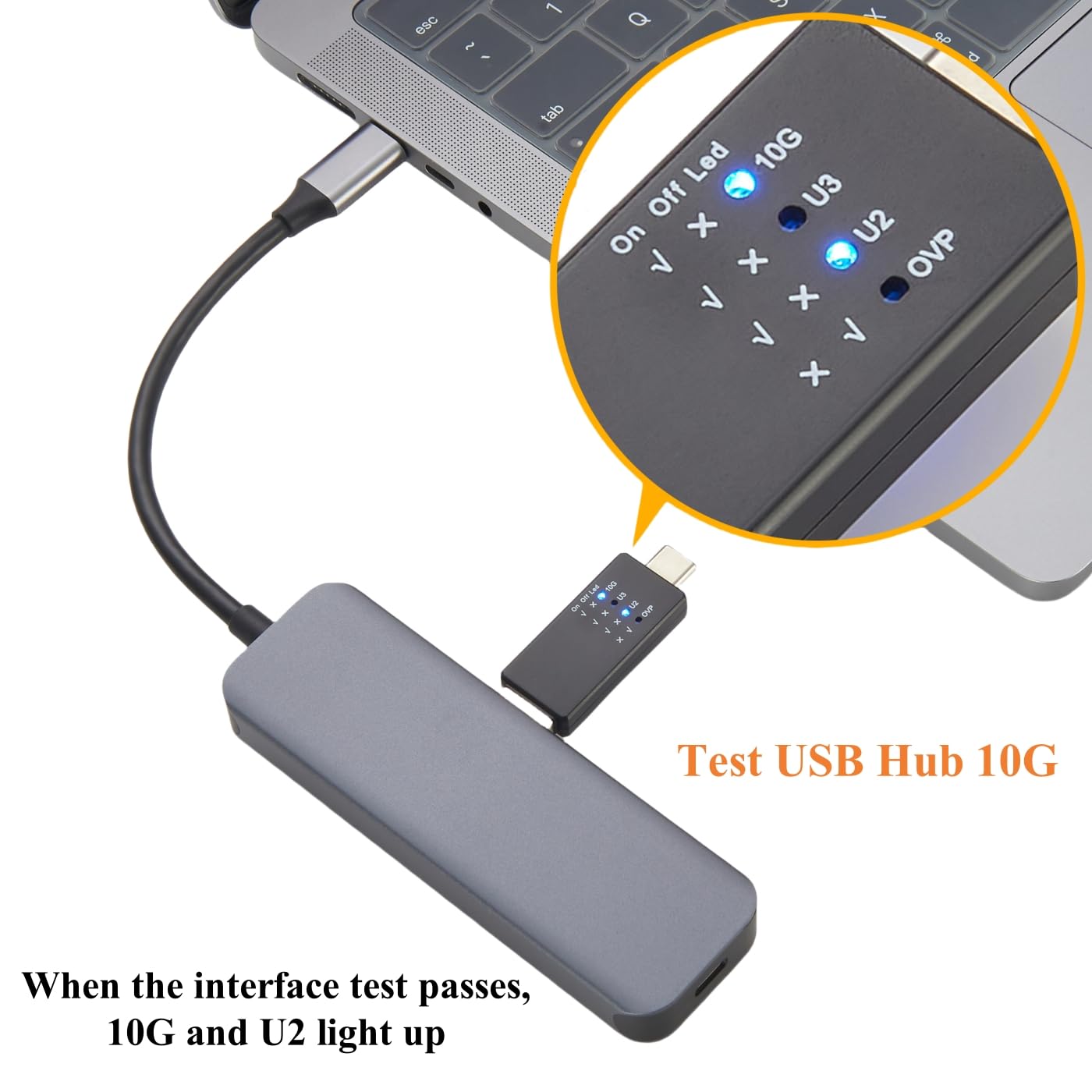
- 10G Indicator: Lights up when a USB 3.1 Gen 2 (10Gbps) connection is detected.
- OVP Indicator: Lights up if an overvoltage condition is detected (voltage > 5V).
Detection Logic:
- When testing a USB 2.0 port: The U2 indicator will light up.
- When testing a USB 3.0 (5G) port: The U3 and U2 indicators will light up.
- When testing a USB 3.1 (10G) port: The 10G and U2 indicators will light up. The U3 indicator will not light up in this scenario.


6.3 Overvoltage Protection (OVP) Indication
The OVP indicator provides a critical safety warning. If the voltage at the test port exceeds 5V, the OVP LED will light up. This alerts the user to a potential overvoltage condition, which could damage connected devices. Disconnect the tester immediately if the OVP indicator illuminates and investigate the power source.
6.4 Testing USB Hubs and Devices
The tester can be used to verify the functionality and speed of USB hubs, mobile hard drives, and USB flash drives. Connect the tester to the device or hub's USB port, and observe the LED indicators to confirm the detected USB standard and voltage status.


7. Maintenance
- Cleaning: Use a soft, dry cloth to clean the exterior of the tester. Avoid using liquid cleaners or solvents.
- Storage: Store the tester in a cool, dry place away from direct sunlight and extreme temperatures.
- Handling: Avoid dropping the device or subjecting it to strong impacts, as this may damage internal components.
8. Troubleshooting
- No LEDs light up: Ensure the tester is fully inserted into a powered USB port. Check if the host device is providing power.
- Incorrect speed detected: Verify that the cable and the host port both support the desired USB standard. Some USB-C to USB-A adapters or cables may only support USB 2.0 or 3.0 speeds.
- OVP indicator lights up: Immediately disconnect the tester. This indicates an overvoltage condition (above 5V) which can damage devices. Investigate the power source or port for faults.
- Intermittent connection: Ensure all connections are secure and free from debris. Try testing with a different cable or port to isolate the issue.
9. Warranty and Support
For any issues, defects, or questions regarding the Plinkwirekb USB 10G Tester, please contact the manufacturer or your point of purchase. Please refer to your purchase documentation for specific warranty terms and contact information. The manufacturer is committed to resolving product-related concerns promptly.