
Introduction
This manual provides essential information for the proper setup, operation, and maintenance of your Meshnology 1.3 Inch OLED Display Module. This module features a 128x64 pixel resolution, IIC/I2C interface, and is driven by the CH1116 controller, making it suitable for various microcontroller projects including Arduino, Raspberry Pi, and ESP32.
Product Features
- High-Definition Visuals: 1.3-inch OLED screen with 128x64 pixel resolution for clear text and graphics.
- CH1116 Driver: Ensures stable and responsive display performance.
- I2C Interface: Simplifies connectivity with microcontrollers, reducing wiring complexity.
- Compact Design: Suitable for integration into various projects, including wearable technology and smart home systems.
- Broad Compatibility: Designed for use with Raspberry Pi, Arduino, and ESP32 platforms.

Image: Overview of the 1.3 Inch OLED Display Module highlighting its bright, clear, self-luminous nature, 128x64 pixel resolution, DC 2.8V-3.3V voltage, and CH1116 driver IC.
Package Contents
The package typically includes:
- OLED Display Module(s)
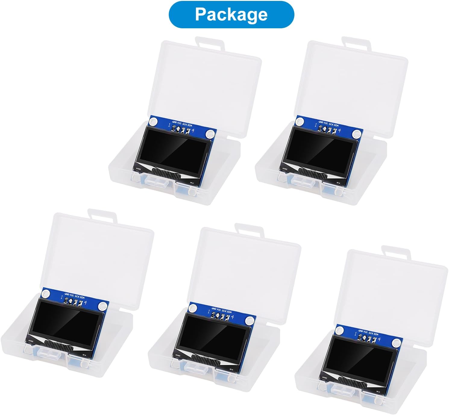
Image: Five 1.3 inch OLED display modules, each housed in a clear protective plastic case, as typically received in a multi-pack.
Specifications
| Specification | Value |
|---|---|
| Display Size | 1.3 inches |
| Resolution | 128x64 pixels |
| Driver IC | CH1116 |
| Interface | IIC / I2C |
| Operating Voltage | DC 2.8V-3.3V |
| Color | White |
| Item Weight | 2.08 ounces (approx.) |
| Package Dimensions | 5.12 x 3.94 x 0.79 inches (approx.) |
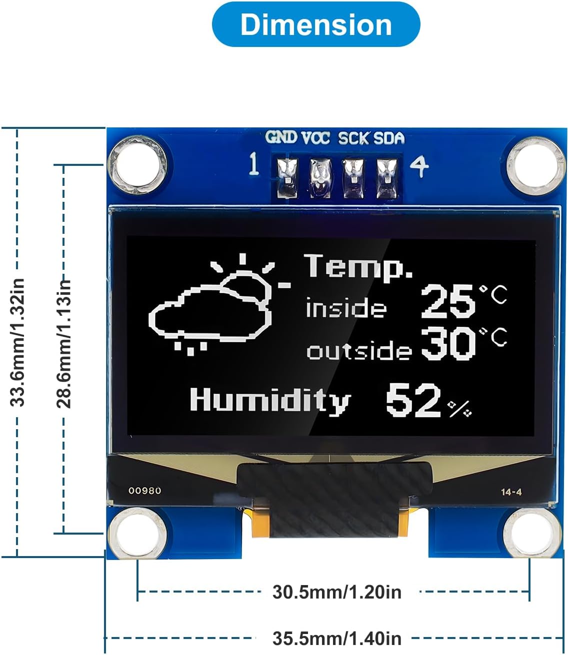
Image: Detailed dimensions of the 1.3 inch OLED display module, showing measurements in millimeters and inches for length and width.
Setup
Pinout Description
The module features a 4-pin header for connection. Understanding these pins is crucial for correct wiring:
| Pin No. | Symbol | Description |
|---|---|---|
| 1 | GND | Ground of Logic Circuit |
| 2 | VCC | Power Supply for Logic (DC 2.8V-3.3V) |
| 3 | SCK | Serial Clock Input (I2C SCL) |
| 4 | SDA | Serial Data Input/Output Pin (I2C SDA) |

Image: Detailed pinout diagram for the 1.3 inch OLED module, showing the GND, VCC, SCK, and SDA pins with their corresponding descriptions.
Wiring Instructions (I2C)
Connect the OLED module to your microcontroller using the I2C interface. Ensure your microcontroller operates at 3.3V logic levels or use a logic level converter if using a 5V microcontroller (e.g., Arduino Uno) to prevent damage.
- Connect GND on the OLED module to the Ground pin on your microcontroller.
- Connect VCC on the OLED module to the 3.3V power supply pin on your microcontroller.
- Connect SCK on the OLED module to the SCL (Serial Clock Line) pin on your microcontroller.
- Connect SDA on the OLED module to the SDA (Serial Data Line) pin on your microcontroller.

Image: Various connection diagrams illustrating how to wire the 1.3 inch OLED module to popular microcontrollers such as Arduino Nano, ESP8266, RAK19007, Raspberry Pi, Arduino Uno, and ESP32.
Operating
Programming and Libraries
To operate the OLED display, you will need to use a compatible library for your chosen microcontroller platform. While the module uses a CH1116 driver, many users have found success with libraries designed for similar OLED drivers like SSD1306 or SH1106, as they often share similar command sets.
- Arduino: Libraries such as Adafruit's SH110X Display Library or U8g2 are commonly used. Ensure to configure the library for 128x64 resolution and the correct I2C address (commonly 0x3C).
- Raspberry Pi / ESP32 (MicroPython): The SH1106 MicroPython Library has been reported to be compatible.
Refer to the specific library documentation for detailed installation and usage instructions. Example code often includes functions for displaying text, drawing shapes, and managing pixels.
Example Applications
The display can be used for a variety of applications, including:
- Displaying sensor data (e.g., temperature, humidity).
- Showing network information (e.g., IP address, CPU usage).
- Creating simple user interfaces for embedded projects.

Image: Two examples of the OLED display in operation. The top image shows a temperature reading (21.8°C) connected to a Raspberry Pi Pico and a sensor. The bottom image displays network information including IP address, CPU usage, memory, and disk space, connected to a Raspberry Pi.
Maintenance
To ensure the longevity and optimal performance of your OLED display module:
- Avoid exposing the module to extreme temperatures or humidity.
- Handle the module by its edges to prevent damage to the display surface or electronic components.
- Keep the display surface clean and free from dust. Use a soft, dry cloth for cleaning if necessary.
- Ensure proper power supply within the specified voltage range (DC 2.8V-3.3V) to prevent overvoltage damage.
Troubleshooting
- Display Not Lighting Up:
- Verify power connections (VCC and GND) and ensure the correct voltage (3.3V) is supplied.
- Check I2C connections (SDA and SCL) for continuity and correct pin assignment.
- Confirm the I2C address in your code matches the module's default address (commonly 0x3C).
- Garbled or Incorrect Display:
- Ensure you are using a library compatible with the CH1116 driver or a known compatible alternative (e.g., SH110X, SSD1306 with appropriate configuration).
- Check that the display resolution (128x64) is correctly set in your library initialization.
- Verify that your microcontroller's logic levels are compatible (3.3V). A 5V signal without a level shifter can cause issues or damage.
- No Communication:
- Perform an I2C scanner sketch to detect if the module is recognized on the bus and to confirm its address.
- Ensure pull-up resistors are correctly configured for the I2C bus, if not already integrated into your microcontroller board.
Warranty and Support
Meshnology products are designed for reliability and durability. For specific warranty information or technical support, please refer to the seller's return policy or contact Meshnology directly through their official channels. Keep your purchase receipt for any warranty claims.