Introduction
This manual provides detailed instructions for the YELUFT USB to TTL Adapter FT232R FT232RL. This device facilitates communication between a computer's USB port and a device requiring TTL serial communication. It features an original FTDI FT232RL chip, ensuring reliable performance across various operating systems. The adapter supports adjustable TTL levels (5V/3.3V) and is powered directly via USB.

Figure 1: YELUFT USB to TTL Adapter, showing the USB connector and pin headers.
Product Features
- FTDI FT232RL Chip: Utilizes the genuine FTDI FT232RL chip for stable and efficient USB to serial communication.
- Adjustable TTL Levels: Supports both 5V and 3.3V TTL logic levels, selectable via a switch.
- USB Powered: Draws power directly from the USB port, eliminating the need for an external power supply.
- Multiple Power Supply Modes: Supports 5V external power, 3.3V external power, or external power supply (3.3V-5V).
- LED Indicators: Equipped with TXD (Transmit), RXD (Receive), and Power LEDs for status monitoring.
- Bent Pin Headers: VCC, GND, TXD, RXD, RTS, CTS pins are conveniently led out with bent pin headers. Additional common pin pads are reserved for flexibility.
- Wide System Compatibility: Compatible with Windows 10, 8, 7, XP, Vista, Windows CE, Mac OS-X, Linux, and Android operating systems.
- Compact Design: Small form factor for easy integration and portability.
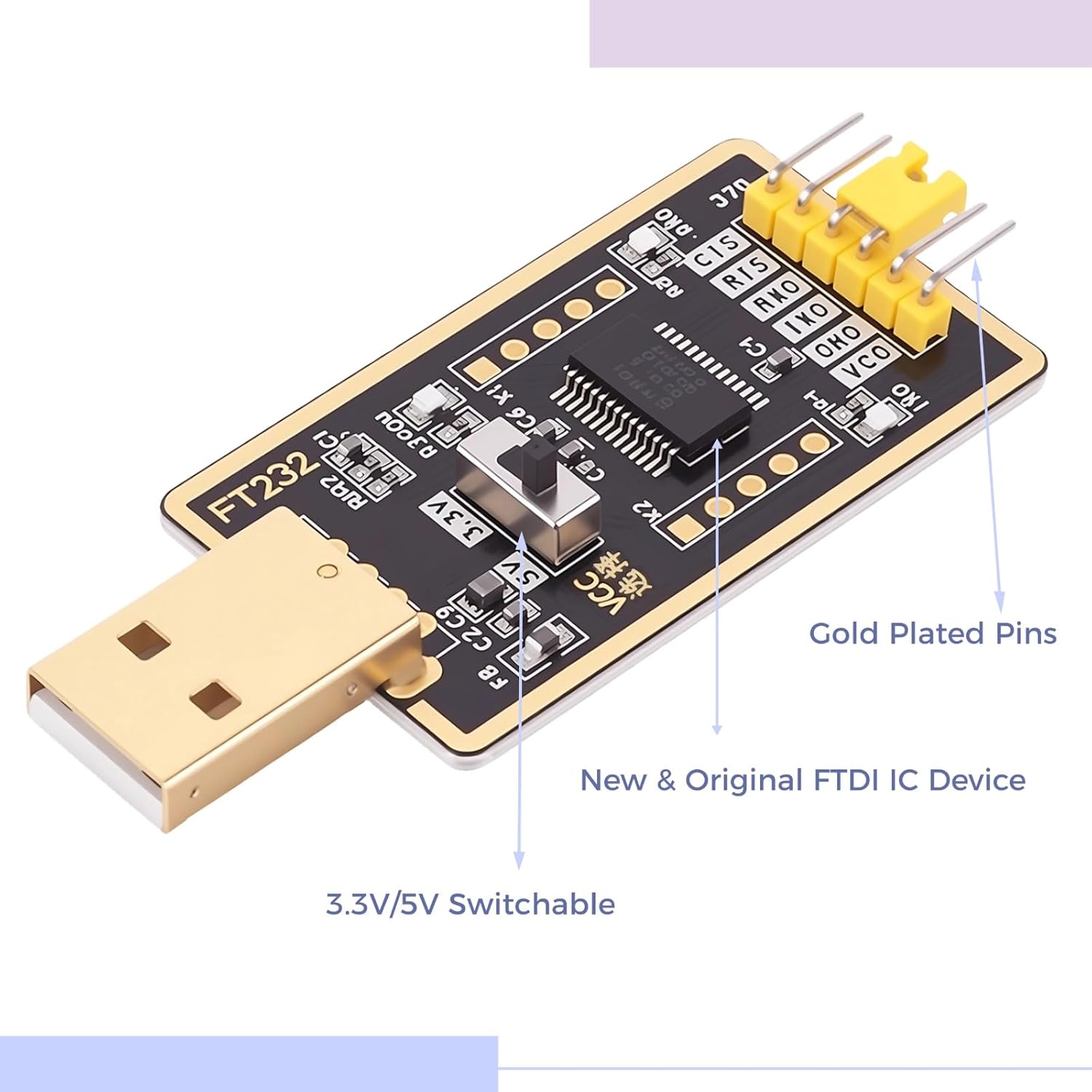
Figure 2: Close-up view of the adapter, showing the 3.3V/5V switch and gold-plated pins.
Setup
- Driver Installation:
For most modern operating systems (Windows 10, Mac OS-X, Linux), drivers for the FTDI FT232RL chip are often installed automatically upon connecting the device. If automatic installation fails, or for older operating systems, download the appropriate VCP (Virtual COM Port) drivers from the official FTDI website (ftdichip.com/drivers/vcp-drivers/). Follow the installation instructions provided by FTDI.
- Connect to Computer:
Plug the USB end of the adapter into an available USB port on your computer. The Power LED on the adapter should illuminate, indicating it is receiving power.
- Select TTL Voltage Level:
Locate the 3.3V/5V switch on the adapter. Set the switch to the desired voltage level (3.3V or 5V) to match the logic level of the device you intend to connect. Ensure this is set correctly before connecting to your target device to prevent damage.

Figure 3: Front and back views of the adapter, showing the voltage selection switch on the front.
- Identify COM Port:
After driver installation, the adapter will appear as a Virtual COM Port (VCP) in your computer's Device Manager (Windows) or equivalent system information utility (Mac/Linux). Note the assigned COM port number for use with serial communication software.
Operating Instructions
The YELUFT USB to TTL Adapter is designed for various serial communication tasks. Below are general guidelines for its operation.
- Pin Connections:
Connect the adapter's pins to your target device according to the following standard:
- TXD (Transmit Data): Connect to the RXD (Receive Data) pin of your target device.
- RXD (Receive Data): Connect to the TXD (Transmit Data) pin of your target device.
- GND (Ground): Connect to the GND (Ground) pin of your target device.
- VCC (Voltage Common Collector): Provides the selected 3.3V or 5V power output. Connect to the VCC/power input of your target device if it requires power from the adapter. Caution: Ensure the voltage matches your device's requirements.
- RTS (Request To Send) / CTS (Clear To Send): These are hardware flow control pins. Use them if your application requires hardware flow control; otherwise, they can be left unconnected.
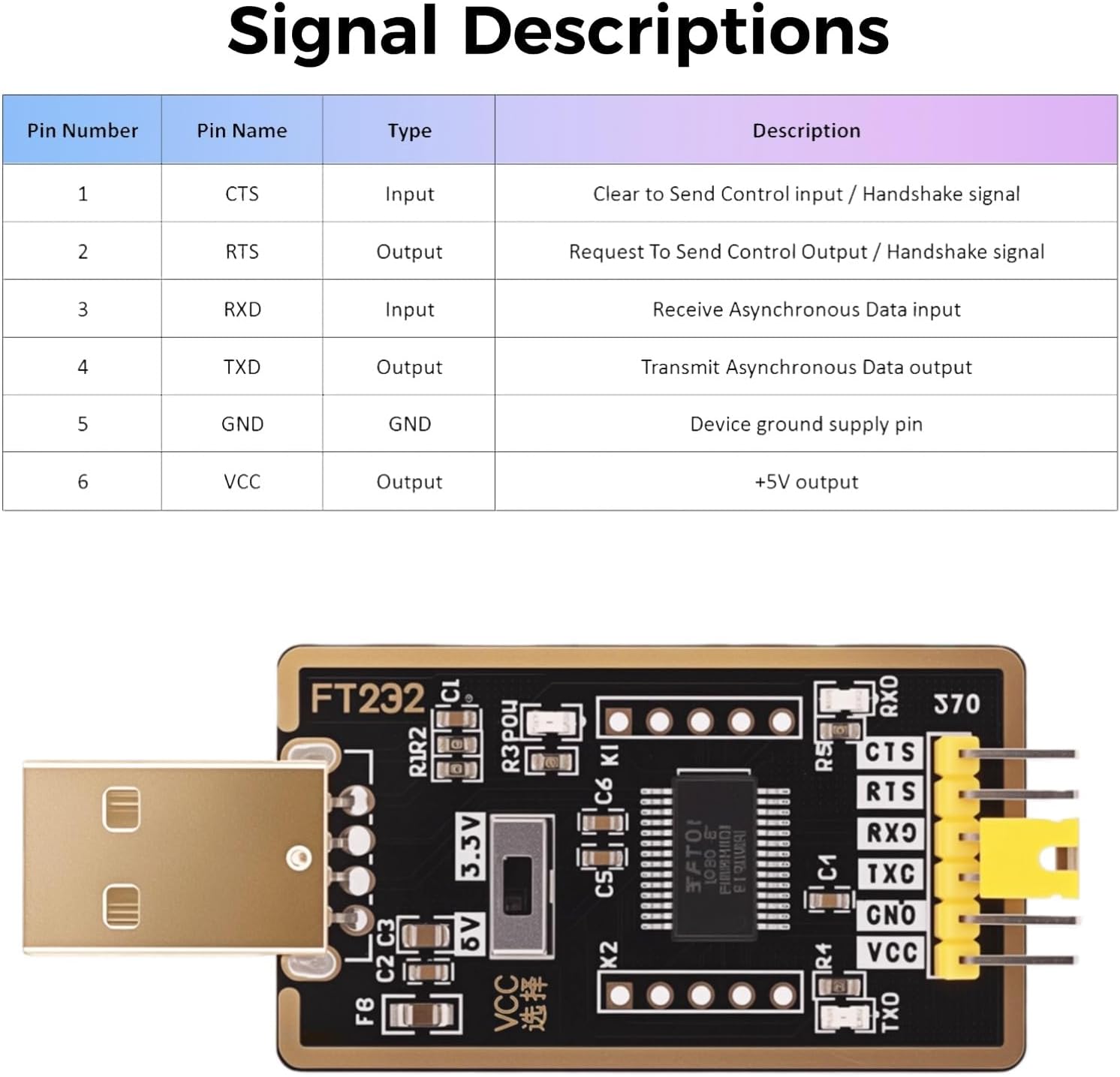
Figure 4: Signal descriptions for the adapter's pin headers.
- Serial Communication Software:
Use a serial terminal program (e.g., PuTTY, Tera Term, Arduino IDE Serial Monitor, minicom on Linux) to communicate with your device. Configure the software with the correct COM port, baud rate, data bits, parity, and stop bits as required by your target device.
- LED Indicators:
- Power LED: Illuminates when the adapter is connected to a USB port and receiving power.
- TXD LED: Flashes when data is being transmitted from the computer via the adapter.
- RXD LED: Flashes when data is being received by the computer via the adapter.
- Typical Applications:
This adapter is suitable for:
- USB-to-serial (RS232/RS422/RS485) conversion (with external level shifters if needed).
- EEPROM programming.
- Vendor ID customization.
- Router/Mprog3.5 recovery.
- GPS module interfacing.
- Firmware updates for various devices (e.g., hard drives, transmitters).
- Set-top box communication.
- Microcontroller programming (Arduino, ESP32, etc.).

Figure 5: Examples of multi-function applications for the adapter.
Maintenance
- Storage: Store the adapter in a dry, cool environment, away from direct sunlight and extreme temperatures.
- Cleaning: Use a soft, dry cloth to clean the adapter. Avoid using liquid cleaners or solvents.
- Handling: Handle the adapter by its edges to avoid touching the electronic components. Do not bend or apply excessive force to the pins or the USB connector.
- Cable Management: Ensure connected cables are not under tension to prevent damage to the adapter's pins or the USB port.
Troubleshooting
- Adapter Not Recognized:
Ensure the adapter is fully plugged into the USB port. Check Device Manager (Windows) or system information for the presence of the FTDI device. If not found, reinstall the FTDI VCP drivers manually from the official FTDI website.
- No Data Transmission/Reception (TXD/RXD LEDs not flashing):
- Verify pin connections: TXD to RXD, RXD to TXD, and GND to GND.
- Confirm the correct COM port is selected in your serial communication software.
- Check that the baud rate, data bits, parity, and stop bits settings in your software match those of your target device.
- Ensure the target device is powered on and functioning correctly.
- Device Not Responding / Damage:
- Verify the 3.3V/5V switch is set to the correct voltage level for your target device. Supplying incorrect voltage can damage the target device or the adapter.
- Ensure the VCC pin is only connected if your target device requires power from the adapter and can handle the selected voltage.
- Avoid short circuits between pins.
- Intermittent Connection:
Try a different USB port on your computer. Ensure all cable connections are secure. Avoid using excessively long or low-quality USB extension cables.
Specifications
| Feature | Detail |
|---|---|
| Model Number | DZ-L001359 |
| Chipset | Original FTDI FT232RL |
| Interface | USB to TTL Serial |
| TTL Logic Levels | Selectable 3.3V / 5V |
| Power Supply | USB Powered (5V), supports 3.3V/5V external power modes |
| LED Indicators | TXD, RXD, Power |
| Compatible OS | Windows 10/8/7/XP/Vista/CE, Mac OS-X, Linux, Android |
| Dimensions (L x W x H) | 2.60" x 1.23" x 0.47" (65mm x 26mm x 12mm approx.) |
| Weight | 0.21 oz / 7g (approx.) |

Figure 6: Product dimensions.
Warranty and Support
For information regarding product warranty, technical support, or customer service, please refer to the documentation included with your purchase or visit the official YELUFT brand store on Amazon: YELUFT Store.
No relevant official product videos were found for this item based on the provided data.