1. Introduction
This manual provides essential information for the safe and efficient operation of the Eujgoov JLS-E-2S-5.5GB-4T Frequency Drive Inverter. Please read this manual thoroughly before installation, operation, or maintenance to ensure proper use and to prevent damage to the device or injury to personnel.
The JLS-E-2S-5.5GB-4T is a high-performance frequency converter designed to convert single-phase AC220V input into three-phase AC220V output, suitable for various motor control applications.

Figure 1: Eujgoov JLS-E-2S-5.5GB-4T Frequency Drive Inverter. This image shows the front and side view of the inverter unit, highlighting its compact design and control panel.
2. Safety Information
WARNING: Read the user manual before operation. Risk of electrical shock. Wait 10 minutes after removing power before servicing.
- Ensure all wiring is performed by qualified personnel in accordance with local and national electrical codes.
- Do not operate the inverter with damaged cables or if the casing is open.
- Always disconnect power and wait for at least 10 minutes for capacitors to discharge before performing any maintenance or inspection.
- This inverter does not support external resistances.
- Avoid operating in environments with excessive dampness, water mist, water droplets, or where metal objects could fall into the unit, as this can cause short circuits.
- If your engine load is large, select an inverter with a higher power rating to prevent overload.
3. Product Overview
3.1 Model Number Breakdown
Understanding the model number helps identify the specific features of your inverter.

Figure 2: Model Number Breakdown. This diagram illustrates how the model number JLS-E-2S-5.5GB-4T is structured, indicating voltage level, machine type, and brake unit information.
- JLS-E: Series designation
- 2S: Voltage level - Single phase
- 5.5GB: Power rating and machine type - 5.5kW, General purpose, with brake unit
- 4T: Output phase - Three phases
3.2 Control Panel Layout
The inverter features an intuitive digital display and a user-friendly keyboard for easy operation and monitoring.
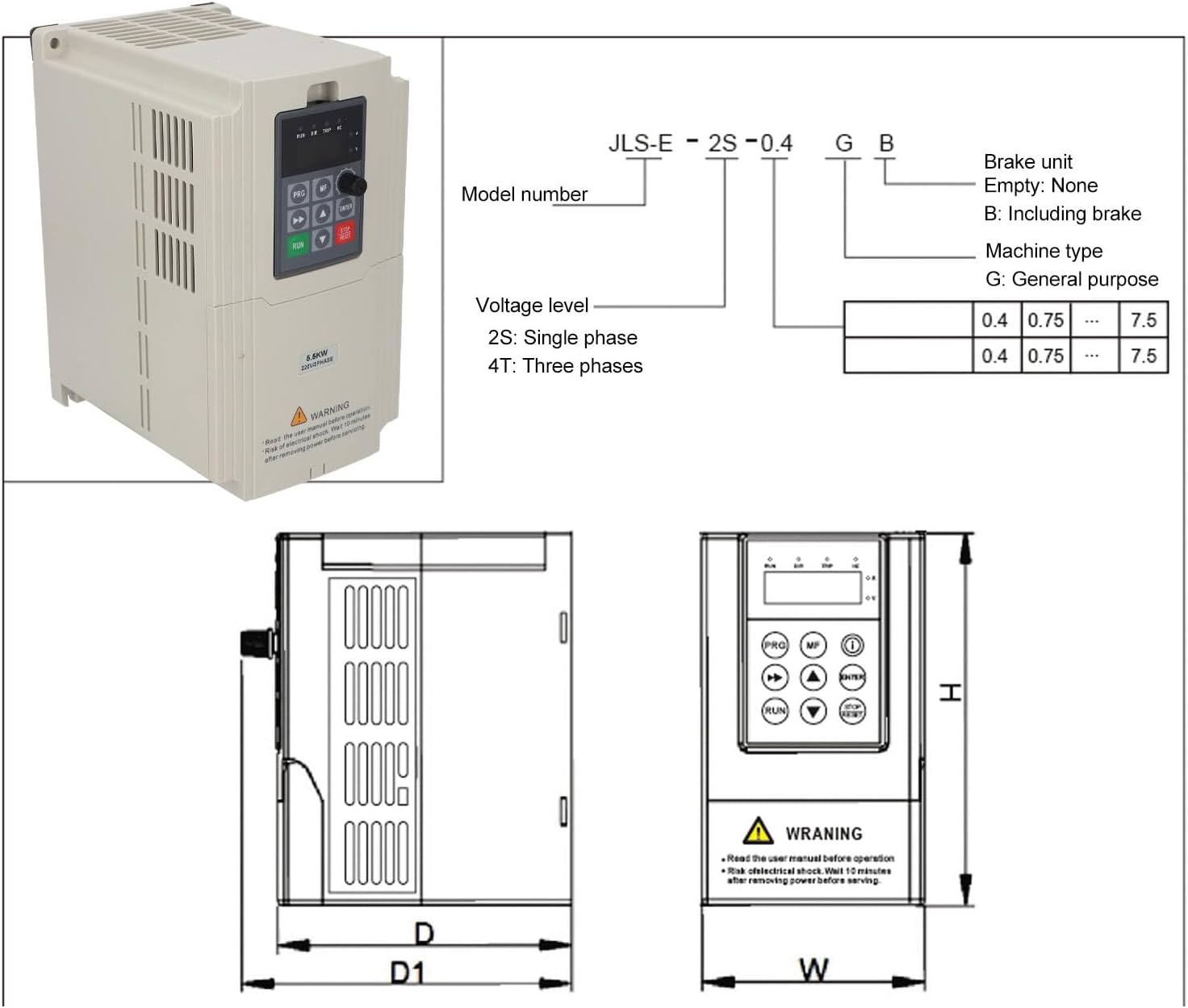
Figure 3: Inverter Control Panel. This image provides a detailed view of the control panel, labeling each button, knob, and indicator light for easy identification and use.
- Status Indication (RUN, DIR, TRIP, HZ): Lights indicating operational status, direction, fault, and frequency display.
- Digital Display: Shows current, voltage, frequency, or parameter values.
- PRG (Menu key): Enters/exits programming mode.
- MF (Multifunction key): Used for various functions depending on the mode.
- Speed Control Knob: Adjusts output frequency/speed.
- Shift Key (<<): Moves cursor or shifts digits during parameter setting.
- Up/Down Select Keys (▲, ▼): Navigate menus or adjust parameter values.
- ENTER (Confirm key): Confirms selections or parameter changes.
- RUN (Run key): Starts the inverter operation.
- STOP/RESET (Stop key/Reset key): Stops operation or clears fault conditions.
4. Specifications
| Parameter | Value |
|---|---|
| Item Type | Frequency Drive Inverter |
| Model | JLS-E-2S-5.5GB-4T |
| Material | ABS, PC |
| Input Voltage | 1 Phase AC220V (±15%) 50/60Hz |
| Output Voltage | 3 Phase AC220V |
| Output Frequency Range | 0-999Hz |
| Output Current | 18A |
| Rated Power | 5.5kW |
| Item Weight | 2.77 Kilograms |
| Communication Interface | 485 (Modbus protocol support) |
5. Setup and Installation
5.1 Mounting
Mount the inverter in a clean, dry, and well-ventilated area, away from direct sunlight, excessive heat, moisture, and corrosive gases. Ensure sufficient clearance around the unit for proper heat dissipation.
5.2 Wiring
All wiring must be performed by a qualified electrician. Ensure power is disconnected before making any connections.

Figure 4: Inverter Connection Points. This image shows the bottom of the inverter with connection terminals, alongside a circuit breaker and a three-phase motor, illustrating typical wiring components.
- Input Power (L, N): Connect the single-phase AC220V power supply to the designated input terminals. Use appropriate circuit breakers for protection.
- Output Power (U, V, W): Connect the three-phase motor to the output terminals U, V, W.
- Grounding (PE): Ensure the inverter is properly grounded to prevent electrical shock.
- Control Terminals: Connect external control signals (e.g., start/stop, speed reference, fault reset) to the digital and analog control terminals as required by your application. Refer to the detailed wiring diagram in the full product manual for specific terminal assignments.
6. Operating Instructions
6.1 Basic Operation
- Power On: After ensuring all connections are secure, apply power to the inverter. The digital display will illuminate.
- Start Motor: Press the RUN button to start the motor. The RUN indicator will light up.
- Adjust Speed: Rotate the Speed Control Knob to adjust the output frequency and motor speed.
- Stop Motor: Press the STOP/RESET button to stop the motor. The RUN indicator will turn off.
6.2 Parameter Programming
The inverter allows for customization of various operational parameters. Refer to the detailed programming guide in the complete manual for a full list of parameters and their functions.
- Enter Programming Mode: Press the PRG key. The display will show a parameter code.
- Navigate Parameters: Use the ▲ and ▼ keys to scroll through parameter codes.
- View/Edit Parameter Value: Press ENTER to view the current value of a selected parameter. Use ▲ and ▼ to change the value. Use the Shift Key (<<) to move between digits.
- Save Changes: Press ENTER again to save the new value.
- Exit Programming Mode: Press the PRG key to return to the main display.
7. Maintenance
Regular maintenance ensures the longevity and reliable operation of your inverter.
- Cleaning: Periodically clean the inverter's exterior and ventilation openings to prevent dust accumulation. Use a soft, dry cloth. Do not use liquid cleaners.
- Inspection: Regularly inspect wiring connections for tightness and signs of wear or damage. Check for any unusual noises or odors during operation.
- Environmental Conditions: Ensure the operating environment remains within specified temperature and humidity ranges. Protect the unit from water, moisture, and corrosive substances.
- Fan Check: Ensure the cooling fan operates freely and is not obstructed.
Always disconnect power and wait 10 minutes before performing any maintenance.
8. Troubleshooting
This section provides basic troubleshooting steps for common issues. For complex problems or issues not listed here, contact technical support.
| Problem | Possible Cause | Solution |
|---|---|---|
| Inverter does not power on | No input power; Blown fuse; Loose connection | Check power supply; Inspect fuses; Verify all wiring connections |
| Motor does not run | Incorrect parameters; Motor wiring error; Overload | Check motor parameters; Verify motor wiring; Reduce load or check motor size |
| Overload trip (TRIP indicator on) | Motor load too high; Inverter undersized | Reduce motor load; Consider a higher power inverter if load is consistently high |
| Abnormal noise from inverter/motor | Loose components; Motor issues; Incorrect frequency settings | Inspect for loose parts; Check motor bearings; Verify frequency settings |
If a fault occurs, the TRIP indicator will illuminate. Press the STOP/RESET button to clear the fault after addressing the cause.
9. Warranty and Support
For warranty information, please refer to the purchase documentation or contact your retailer. Technical support is available through the manufacturer or authorized service centers. Please have your model number (JLS-E-2S-5.5GB-4T) and purchase details ready when contacting support.