Introduction
This manual provides essential information for the proper setup, operation, and maintenance of the YELUFT AMG8833 IR 8x8 Infrared Thermal Imager Module. Please read this manual thoroughly before using the device to ensure optimal performance and safety.
Product Overview
The YELUFT AMG8833 is a compact 8x8 array infrared thermal imager sensor designed for integration with microcontrollers such as Raspberry Pi and Arduino. It provides 64 individual infrared temperature readings via an I2C interface, enabling applications like human detection and mini thermal imaging.
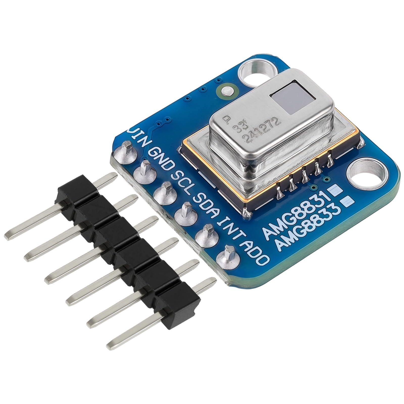
Figure 1: The AMG8833 module held between fingers, demonstrating its compact size.
Key Features:
- 8x8 array of infrared heat sensors for 64 individual temperature readings.
- I2C communication interface for easy integration with microcontrollers.
- Configurable interrupt pin for threshold-based event triggering.
- Compact design suitable for various embedded projects.
What's Included:
- 1 x AMG8833 IR 8x8 Infrared Thermal Imager Module
- 1 x Instruction Manual (this document)

Figure 2: Front and back view of the AMG8833 module.
Specifications
The following table details the technical specifications of the AMG8833 Infrared Thermal Imager Module:
| Parameter | Value |
|---|---|
| Power Supply | 3V - 5V |
| Accuracy | ±2.5°C (±4.5°F) |
| Detection Range (Humans) | Up to 7 meters (23 feet) |
| Maximum Frame Rate | 10Hz |
| Temperature Measurement Range | 0°C to 80°C (32°F to 176°F) |
| Interface | I2C |
| Item Weight | 9.98 g |
| Parcel Dimensions | 13 x 11.99 x 3 cm |
| Model Number | GY-AMG8833 |
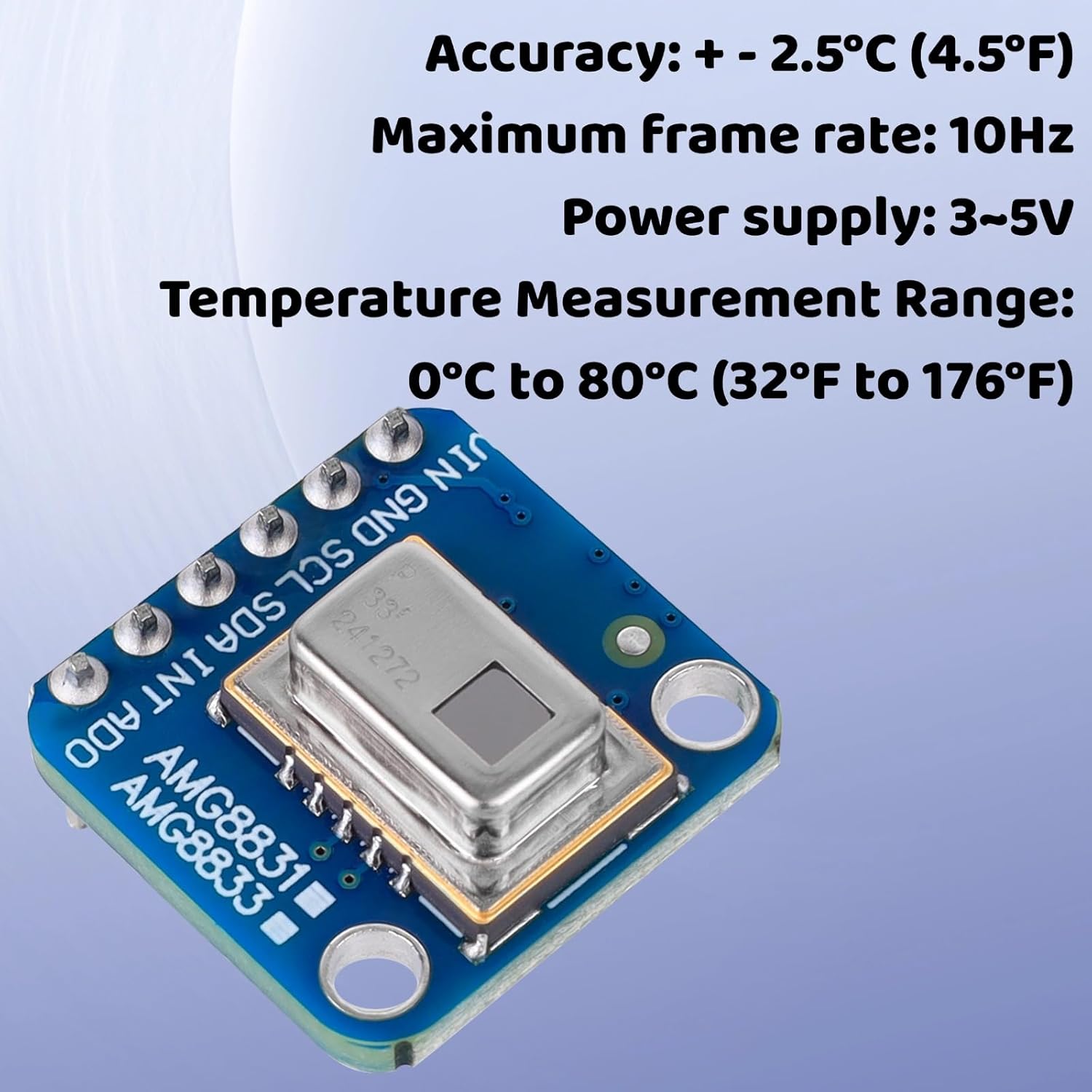
Figure 3: Key operational parameters of the AMG8833 module.

Figure 4: Physical dimensions and weight of the AMG8833 module.
Setup and Connection
Power Supply:
The AMG8833 module requires a power supply between 3V and 5V. Connect the power source to the VIN and GND pins.
I2C Communication:
The module communicates via the I2C protocol. Connect the SCL (Serial Clock) and SDA (Serial Data) pins to the corresponding I2C pins on your microcontroller (e.g., Raspberry Pi, Arduino, ESP8266).
Optional Connections:
- INT (Interrupt): This pin can be configured to trigger an interrupt on your microcontroller when a pixel's temperature exceeds or falls below a set threshold.
- ADO (Address Select): This pin allows for selecting the I2C address, enabling the use of multiple AMG8833 modules on the same I2C bus.
Wiring Diagram:
Refer to the following diagram for typical wiring connections:

Figure 5: Wiring diagram for the AMG8833 module.
Operating Instructions
Data Acquisition:
Once connected, the module can be initialized and read using your microcontroller's I2C library. The sensor provides 64 individual temperature readings (an 8x8 array) which can be accessed sequentially.
Temperature Readings:
The temperature measurement range is from 0°C to 80°C (32°F to 176°F) with an accuracy of ±2.5°C (±4.5°F). Each pixel's reading represents the infrared temperature of its corresponding area.
Frame Rate:
The maximum frame rate for data acquisition is 10Hz, meaning you can obtain up to 10 full 8x8 temperature arrays per second.
Interrupt Functionality:
The configurable interrupt pin can be programmed to alert your microcontroller when specific temperature conditions are met, such as a sudden change in temperature or a temperature exceeding a predefined limit. This is useful for event-driven applications like motion or presence detection.
Maintenance
The AMG8833 module is designed for low maintenance. To ensure longevity and accurate performance:
- Keep the sensor surface clean and free from dust or obstructions.
- Avoid exposing the module to extreme temperatures, humidity, or corrosive environments beyond its specified operating range.
- Handle the module with care to prevent physical damage to the sensor or PCB.
Troubleshooting
No Data or Incorrect Readings:
- Check Connections: Verify all VIN, GND, SCL, and SDA connections are secure and correctly wired according to the diagram.
- Power Supply: Ensure the power supply is within the 3V-5V range and stable.
- I2C Address: Confirm the correct I2C address is being used in your code. The default address is typically 0x68 or 0x69, depending on the ADO pin state.
- Library Compatibility: Ensure you are using a compatible I2C library for your microcontroller and the AMG8833 sensor.
Sensor Not Detected:
- I2C Scanner: Use an I2C scanner sketch (available for Arduino) or tool (for Raspberry Pi) to confirm the module is detected on the I2C bus and identify its address.
- Wiring: Double-check SCL and SDA lines for shorts or open circuits.
Warranty and Support
For warranty information and technical support, please refer to the seller's policies or contact YELUFT customer service through the platform where the product was purchased. Keep your purchase receipt for warranty claims.