1. Introduction
This manual provides detailed instructions for the installation, operation, and maintenance of the eletechsup Industrial DC Motor Controller, Model IO56D02. This controller is designed for precise PWM speed control of brushed DC motors, offering 9 distinct operating modes and intelligent limit protection. It is suitable for various applications including linear actuators, conveyors, and smart home automation systems.
Please read this manual thoroughly before operating the device to ensure safe and efficient use.
2. Safety Information
- Ensure the power supply voltage matches the controller's specified voltage (DC 12V for this version).
- Always disconnect power before making any wiring connections or disconnections.
- Avoid short circuits between terminals.
- Do not exceed the maximum load current of 4.5A.
- Operate the controller within its specified environmental conditions.
- This device is intended for use with brushed DC motors only.
- Seek professional assistance if you are unsure about any wiring or operational procedures.
3. Product Overview
The eletechsup IO56D02 is a compact and versatile DC motor controller. Below is an image of the controller board with key components and pin descriptions.
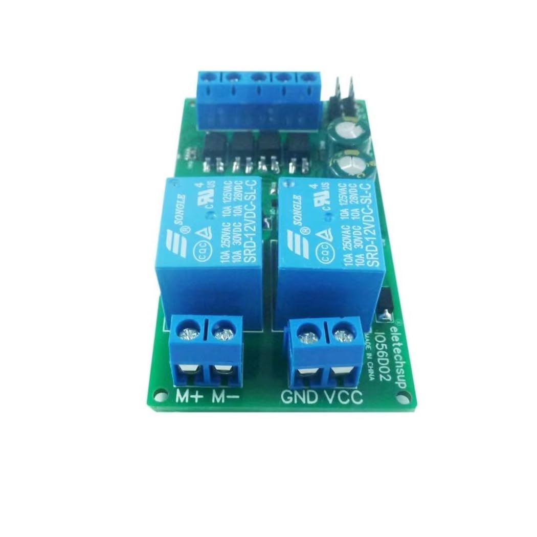
Figure 1: eletechsup IO56D02 DC Motor Controller Board (12V Version). This image displays the green circuit board with blue screw terminals for power, motor, and signal connections, along with two blue Songle relays and other electronic components. The "12V" label is prominently displayed.
3.1 Pin Description
| Pin | Description |
|---|---|
| VCC | Power Supply Positive (+) |
| GND | Power Supply Negative (-) |
| M+ | Motor Positive (+) Output |
| M- | Motor Negative (-) Output |
| GND (Trigger) | Trigger Signal Negative (-) |
| K1 | Forward Rotation Input Control (Active Low) |
| K2 | Reverse Rotation Input Control (Active Low) |
| S1 | Forward Limit Signal Input (Normally Open) |
| S2 | Reverse Limit Signal Input (Normally Open) |
The signal input terminals (K1, K2, S1, S2) accept active low signals (NPN). Signal sources can include micro switches, induction sensors, infrared sensors, metal sensors, remote control modules, or single-chip microcontrollers.
4. Setup
4.1 Power Requirements
- Working Voltage: DC 12V (for this version). The power supply voltage range is DC 11-15V.
- Power Supply Type: Use a DC power source such as a switching power supply, DC output transformer, lead-acid battery, lithium battery, or solar battery.
- Power Connection: Connect the positive wire to the "VCC" terminal and the negative wire to the "GND" terminal. Ensure correct polarity; reversing poles can damage the device.
- Power Capacity: The power supply capacity must be at least three times the motor's power (Power Supply Power ≥ Motor Load × 3).
4.2 Motor Requirements
- Motor Type: This controller is designed exclusively for brushed DC motors.
- Motor Connection: Connect the motor wires to the "M+" and "M-" terminals.
- Rated Power (12V Version): The rated power of the DC motor should be less than 50W, with a maximum limit of 100W.
4.3 Wiring Reference Diagrams
The following diagrams illustrate common wiring configurations for the controller.
Wiring Diagram 1: Two-Position Reciprocating Motion
This configuration is for applications requiring the motor to move back and forth in a straight line between two positions.
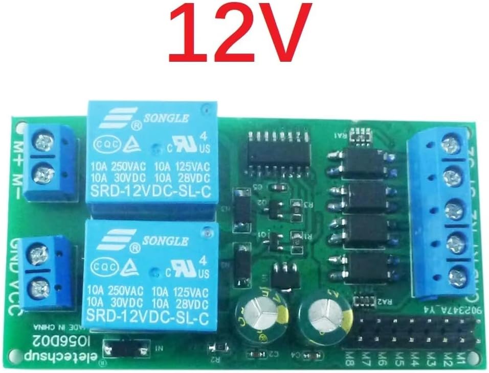
Figure 2: Wiring Diagram for Two-Position Reciprocating Motion. This diagram illustrates how to connect the DC motor controller for applications where a motor needs to move between two defined points, typically using limit switches for position detection.
Wiring Diagram 2: Independent Forward/Reverse Start
In this setup, each start command initiates a single forward or reverse operation independently.
(Note: A specific image for Wiring Diagram 2 was not provided. Please refer to the product documentation or contact support for visual guidance.)
Wiring Diagram 3: Forward and Reverse Rotation per Start
This diagram shows a configuration where each start command triggers both a forward and a reverse rotation sequence.
(Note: A specific image for Wiring Diagram 3 was not provided. Please refer to the product documentation or contact support for visual guidance.)
5. Operating Modes
The controller offers 9 distinct operating modes, selectable based on application requirements. The default mode is Mode 0.
Mode 0: Self-locking Mode (Default)
- A single trigger initiates and maintains motor operation.
- If a reverse signal is received during forward rotation, the motor stops for 0.3 seconds before reversing.
- Limit signals have priority: a forward limit signal immediately stops forward rotation.
- Motor cannot start in a direction if its corresponding limit signal is active (e.g., cannot start forward if forward limit is active).
- Forward and reverse signals are active low (short-term 0V level).
- Limit signals are normally open (e.g., closing SW1 or connecting to low level prevents forward rotation).
- Only one limit signal is effective at a time; simultaneous limit signals in one direction will not stop the motor.
Mode 1: Automatic Start Version of Mode 0
- Adds an automatic power-on start function to Mode 0.
- Upon power-up, the module automatically starts forward rotation.
- Ideal for applications requiring automatic motion between two points upon power activation.
Mode 2: Momentary Mode
- Motor rotates forward as long as a forward signal is present.
- Motor reverses as long as a reverse signal is present.
- Motor stops when no forward or reverse signal is present.
- Forward limit stops forward rotation; reverse limit stops reverse rotation.
- Removing limit signals does not restore rotation; a new rotation signal is required.
Mode 3: Level-Driven Mode (H-Bridge Functionality)
- Functions similarly to an H-bridge, driven by signal levels.
- Forward rotation occurs when a forward signal is present and no forward limit is active.
- Reverse rotation occurs when a reverse signal is present and no reverse limit is active.
- Forward rotation has priority if both forward and reverse conditions are met.
- Responds to real-time signal levels. If forward signal is removed while reverse signal remains, motor reverses.
- Limit inputs are invalid while the motor is rotating; they cannot stop the motor in this mode.
Mode 4: Start/Stop Mode
- Similar to Mode 0, but with modified start/stop logic.
- If forward rotation is active, inputting the forward signal again immediately stops it.
- If reverse rotation is active, inputting the reverse signal again immediately stops it.
- Example: Forward signal >>> forward rotation; input forward signal again >>> immediate stop.
Mode 5: Limit Signal Edge-Triggered Mode
- Similar to Mode 0, but limit signals are only valid for the current event (leading edge).
- After starting forward rotation, it stops upon encountering a forward limit signal.
- Even if the forward limit signal remains active after stopping, forward rotation can be restarted by re-inputting the forward rotation signal.
- Useful for applications where a single press completes one cycle (e.g., one full rotation).
Mode 6: One-Key Switch Mode
- Similar to Mode 0, but uses a single input for sequential operations.
- First trigger of the forward rotation signal initiates forward rotation.
- Second trigger of the forward rotation signal initiates reverse rotation.
- Reverse rotation signal input is invalid in this mode.
- Forward rotation stops at forward limit; reverse rotation stops at reverse limit.
Mode 7: Forward with Signal, Reverse without Signal
- Motor rotates forward when a forward rotation signal is present.
- Motor reverses when no forward rotation signal is present.
- Reverse rotation signal input is invalid and cannot be used with other signals.
- Forward limit stops forward rotation; reverse limit stops reverse rotation.
- Only one limit signal is effective at a time; simultaneous limit signals in one direction will not stop the motor.
Mode 8: Self-locking - Limit Normally Closed Mode
- Similar to Mode 0, but with normally closed limit signals.
- Forward rotation cannot start if there is no signal input to the forward limit (i.e., limit is open).
- Forward rotation can only start when the forward limit signal is active (i.e., limit is closed).
6. Maintenance
- Keep the controller clean and free from dust and moisture.
- Regularly inspect wiring connections for looseness or damage.
- Ensure adequate ventilation to prevent overheating, especially during continuous operation at high loads.
- Do not attempt to repair the internal components unless you are a qualified technician.
7. Troubleshooting
- Motor not responding:
- Check power supply connections (VCC, GND) and ensure correct voltage.
- Verify motor connections (M+, M-).
- Confirm signal input (K1, K2) is active low and correctly applied.
- Check if limit switches (S1, S2) are active, preventing motor movement in the desired direction (especially in Mode 0).
- Ensure the motor's power requirements are within the controller's limits.
- Intermittent operation:
- Inspect all wiring for loose connections.
- Check for unstable power supply.
- Ensure signal inputs are stable and not fluctuating.
- Overheating:
- Verify the motor load does not exceed the controller's maximum current (4.5A).
- Ensure the power supply capacity is sufficient (≥ motor load x 3).
- Provide adequate ventilation around the controller.
8. Specifications
| Parameter | Value |
|---|---|
| Model | IO56D02 |
| Working Voltage | DC 12V (Range: DC 11-15V) |
| Applicable Motor | Brushed DC Motor |
| Max Load Current | 4.5A |
| Signal Input | Active Low (NPN) |
| Working Modes | 9 Optional Modes (Momentary, Self-locking, etc.) |
| Quiescent Current | 4mA |
| Operating Current (Forward/Reverse) | 40mA (excluding motor) |
| Dimensions (L*W*H) | 75mm * 40mm * 19mm |
| Weight | 37.6 grams |
| Rated Motor Power (12V) | < 50W (Limit: 100W) |
9. Warranty and Support
This product comes with a standard manufacturer's warranty. For specific warranty terms and conditions, please refer to the product packaging or contact your retailer.
For technical support, troubleshooting assistance, or inquiries regarding product functionality, please visit the eletechsup Store on Amazon or contact their customer service directly.


