1. Introduction
This manual provides essential information for the safe and effective use of the OETIBUFA P4100 Oscilloscope Probe. The P4100 is a high-voltage, high-bandwidth probe designed for use with oscilloscopes, offering a 100:1 attenuation ratio and a 100MHz bandwidth. It is suitable for measuring high voltage signals up to 2KV (Vp-p).
2. Product Overview
2.1 Key Features
- Model: P4100
- Bandwidth: 100MHz
- Attenuation Ratio: 100X
- Maximum Input Voltage: 2000V (Vp-p)
- Input Resistance: 100MΩ ±2% (100X)
- Input Capacity: 6PF (100X)
- Compensation Range: 10-35PF
- Cable Length: 1.2 meters
- Safety BNC Connector
- Adjustable Attenuation
2.2 Components and Visuals
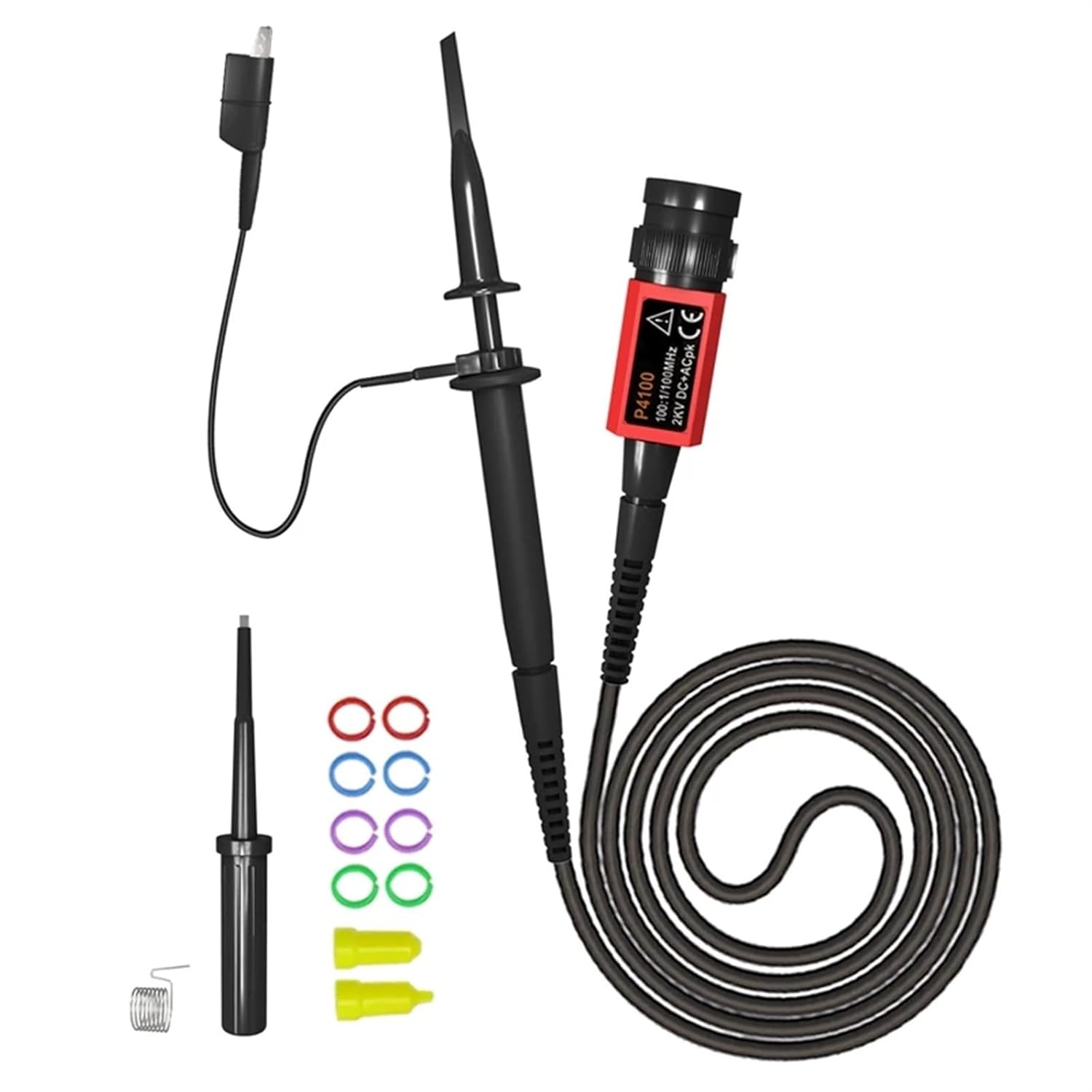
Figure 1: The P4100 Oscilloscope Probe shown with its included accessories, including the probe body, ground lead, adjustment tool, and color rings.

Figure 2: A detailed view of the P4100 probe's BNC connector, which features clear labeling for its model (P4100), bandwidth (100MHz), attenuation (100:1), and maximum voltage (2KV DC+ACpk). Also shown are the included color rings for probe identification.

Figure 3: The P4100 probe connected to a circuit board, illustrating its use in a testing environment. The image also highlights the probe's attenuation switch, which allows selection of the 100X attenuation setting.

Figure 4: A close-up view of the P4100 probe tip, showing the retractable hook attachment. This hook allows for secure connection to test points, preventing accidental disconnections during measurements.
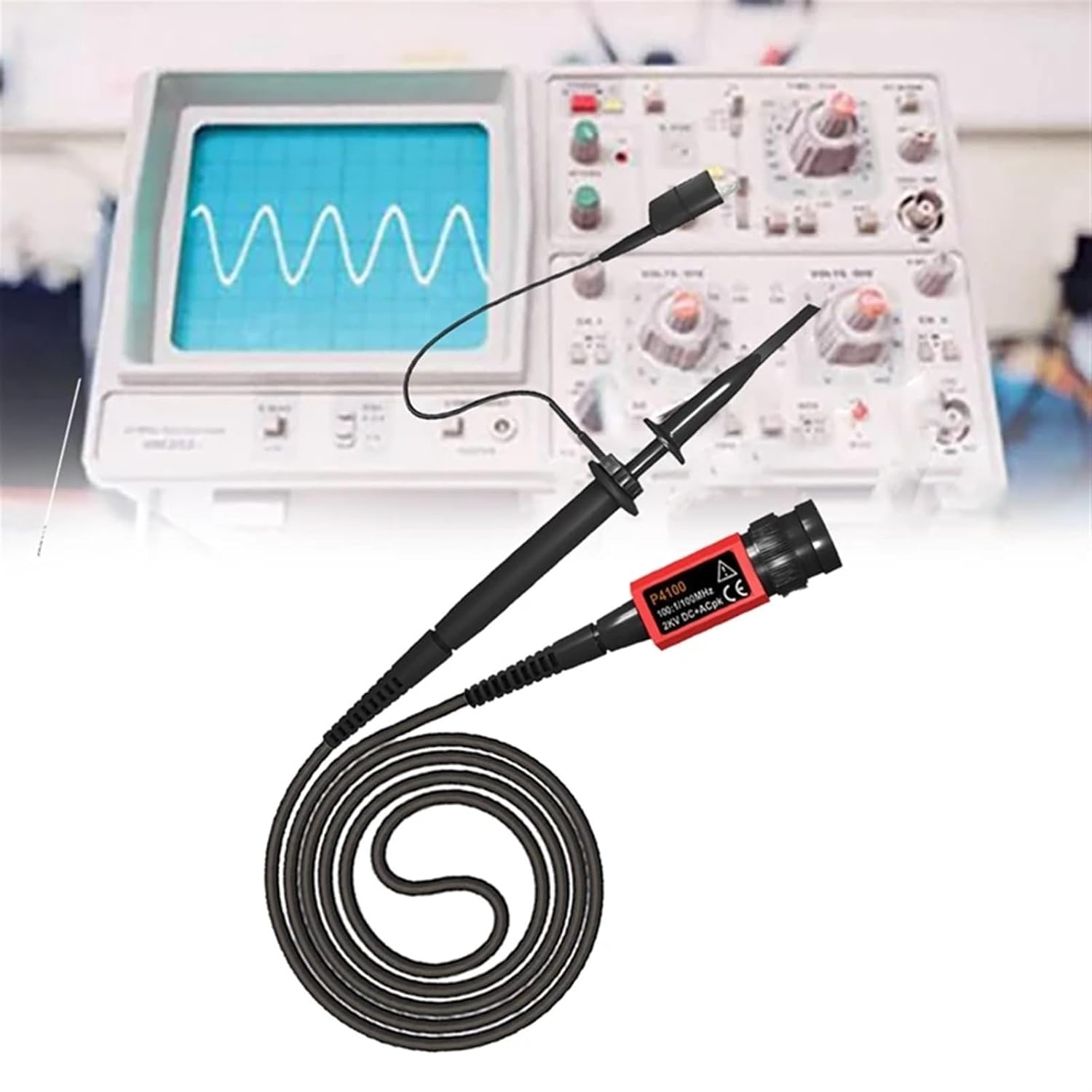
Figure 5: The P4100 probe connected to an oscilloscope, demonstrating a typical setup for signal measurement. The probe's BNC connector securely attaches to the oscilloscope input.

Figure 6: The P4100 probe in use, connected to a circuit board to measure signals. This illustrates the practical application of the probe in electronic testing and diagnostics.
3. Specifications
| Parameter | Value |
|---|---|
| Model | P4100 |
| Bandwidth | 100MHz |
| Rise Time | 3.5 ns |
| Attenuation Ratio | 100X |
| Input Resistance (100X) | 100MΩ ±2% |
| Input Capacity (100X) | 6PF |
| Maximum Input Voltage (Vp-p) | 2000V |
| Compensation Range | 10-35PF |
| Cable Length | 1.2 meters |
| Material | PVC+Metal |
| Color | Black |
4. Setup
- Connect to Oscilloscope: Insert the BNC connector of the P4100 probe into the input channel of your oscilloscope. Ensure a secure connection.
- Attach Ground Lead: Connect the alligator clip of the probe's ground lead to the ground terminal of your oscilloscope or the circuit under test. A proper ground connection is crucial for accurate measurements and safety.
- Select Attenuation: The P4100 probe has a fixed 100X attenuation. Set your oscilloscope's input channel to match this attenuation (e.g., if the probe is 100X, set the oscilloscope to 100X or adjust the vertical scale accordingly).
- Probe Compensation:
Before taking measurements, it is recommended to compensate the probe to match the input impedance of your oscilloscope.
- Connect the probe tip to the oscilloscope's calibration output (usually 1kHz, 5Vp-p) and the ground clip to the ground terminal.
- Observe the square wave on the oscilloscope screen.
- Use the provided adjustment tool to turn the compensation screw on the probe body until the square wave corners are flat (neither rounded nor peaked).
5. Operating Instructions
The P4100 probe is designed for high voltage measurements. Always ensure the probe's voltage rating is appropriate for the circuit being tested.
- Connect to Circuit: After connecting the probe to the oscilloscope and performing compensation, connect the probe tip to the desired test point on the circuit. Ensure the ground clip is securely connected to the circuit's ground reference.
- Observe Waveform: Adjust the oscilloscope's vertical and horizontal scales to properly display the waveform. Remember that the probe attenuates the signal by 100X, so the actual voltage at the test point is 100 times the voltage displayed on the oscilloscope screen.
- Using the Hook Tip: For hands-free measurements, extend the retractable hook from the probe tip to securely latch onto component leads or test points.
- Color Rings: Use the included color rings to identify multiple probes if you are using more than one, or to differentiate channels on your oscilloscope.
6. Maintenance
- Cleaning: Clean the probe body with a soft, dry cloth. Do not use abrasive cleaners or solvents. Ensure the probe is disconnected from all power sources before cleaning.
- Storage: Store the probe in a clean, dry environment, away from direct sunlight and extreme temperatures. Keep the probe tip protected when not in use.
- Inspection: Regularly inspect the probe cable, BNC connector, and probe tip for any signs of damage, such as cracks, frayed wires, or bent pins. Do not use a damaged probe.
7. Troubleshooting
- No Signal on Oscilloscope:
- Ensure the probe is securely connected to both the oscilloscope and the circuit under test.
- Verify the oscilloscope channel is enabled and the vertical scale is appropriate.
- Check the ground connection.
- Confirm the circuit under test is powered and generating a signal.
- Distorted Waveform:
- Perform probe compensation as described in the Setup section.
- Ensure the probe's bandwidth is sufficient for the signal being measured.
- Check for proper grounding.
- Incorrect Voltage Reading:
- Verify that the oscilloscope's vertical scale is correctly set to account for the probe's 100X attenuation.
- Ensure the probe is not damaged.
8. Package Contents
The P4100 Oscilloscope Probe package typically includes the following items:
- 1 x P4100 Oscilloscope Probe
- 1 x Ground Lead with Alligator Clip
- 1 x Adjustment Tool
- 4 x Color Rings
9. Safety Information
WARNING: High voltage can be lethal. Always exercise extreme caution when working with electrical circuits.
- Do not exceed the maximum input voltage rating of 2000V (Vp-p) for the P4100 probe.
- Always ensure the probe's ground lead is securely connected to the circuit's ground before connecting the probe tip to a live circuit.
- Never touch the probe tip or exposed conductors when the probe is connected to a live circuit.
- Use only with oscilloscopes that have a properly grounded chassis.
- Inspect the probe for any damage before each use. Do not use if the cable is frayed, the connector is loose, or the probe body is cracked.
- If working in a high-voltage environment, ensure you are properly insulated and follow all relevant safety procedures.
- This probe is intended for professional use by trained personnel.
10. Warranty and Support
Specific warranty information for the OETIBUFA P4100 Oscilloscope Probe is not provided in this manual. For details regarding warranty coverage, technical support, or service, please contact the manufacturer or your point of purchase directly.
Manufacturer: OETIBUFA


