1. Introduction
This manual provides essential instructions for the safe and effective operation, assembly, and maintenance of your Generic Manual Jack Strut Spring Compressor. This tool is designed for compressing automotive coil springs during strut and shock absorber service. Please read this manual thoroughly before use to ensure proper function and safety.

Image 1: Overview of the Generic Manual Jack Strut Spring Compressor. This image displays the complete assembly of the red-colored spring compressor, featuring the main vertical column, hydraulic jack mechanism, and spring clamping arms.
2. Safety Information
WARNING: Improper use of this equipment can result in serious injury or death. Always follow safety precautions.
- Always wear appropriate personal protective equipment, including safety glasses and gloves.
- Ensure the compressor is placed on a stable, level, and non-slip surface.
- Anchor the compressor to the ground using the pre-drilled holes in the base for maximum stability, especially when compressing heavy springs.
- Never exceed the rated compression force of 1 ton or the 4.5 ton hydraulic load capacity.
- Ensure the spring is securely seated in the clamps and the safety chain is properly engaged before applying pressure.
- Do not attempt to compress damaged or corroded springs.
- Keep hands and other body parts clear of moving parts during operation.
- Inspect the compressor for damage or wear before each use. Do not use if any components are damaged.
- Release pressure slowly and carefully.
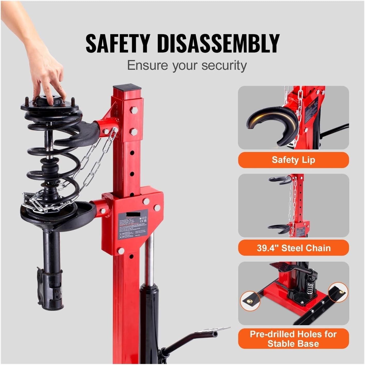
Image 2: Safety features for secure spring disassembly. This image highlights the safety lip on the clamps, the 39.4-inch steel safety chain, and the pre-drilled holes in the stable base for anchoring, all designed to enhance user security during operation.
3. Components and Features
The Generic Manual Jack Strut Spring Compressor consists of several key components designed for efficient and safe operation:
- Main Column: The vertical support structure made of Q235 reinforced steel.
- Hydraulic Jack: Provides the compression force, featuring a leak-proof pump and dampened hydraulic rod.
- Spring Clamps (Clasps): Two sets (small and large) made of ductile cast iron for securing springs.
- Safety Chain: An extended 39.4-inch chain to secure the spring during compression.
- H-shaped Base: Provides stability and includes pre-drilled holes for anchoring.
- Adjustment Holes: 8 positioning holes on the column for adjusting clamp height.
- Safety Tongue/Lip: Integrated into the clamps to prevent spring detachment.
- Release Pedal: For controlled release of hydraulic pressure.
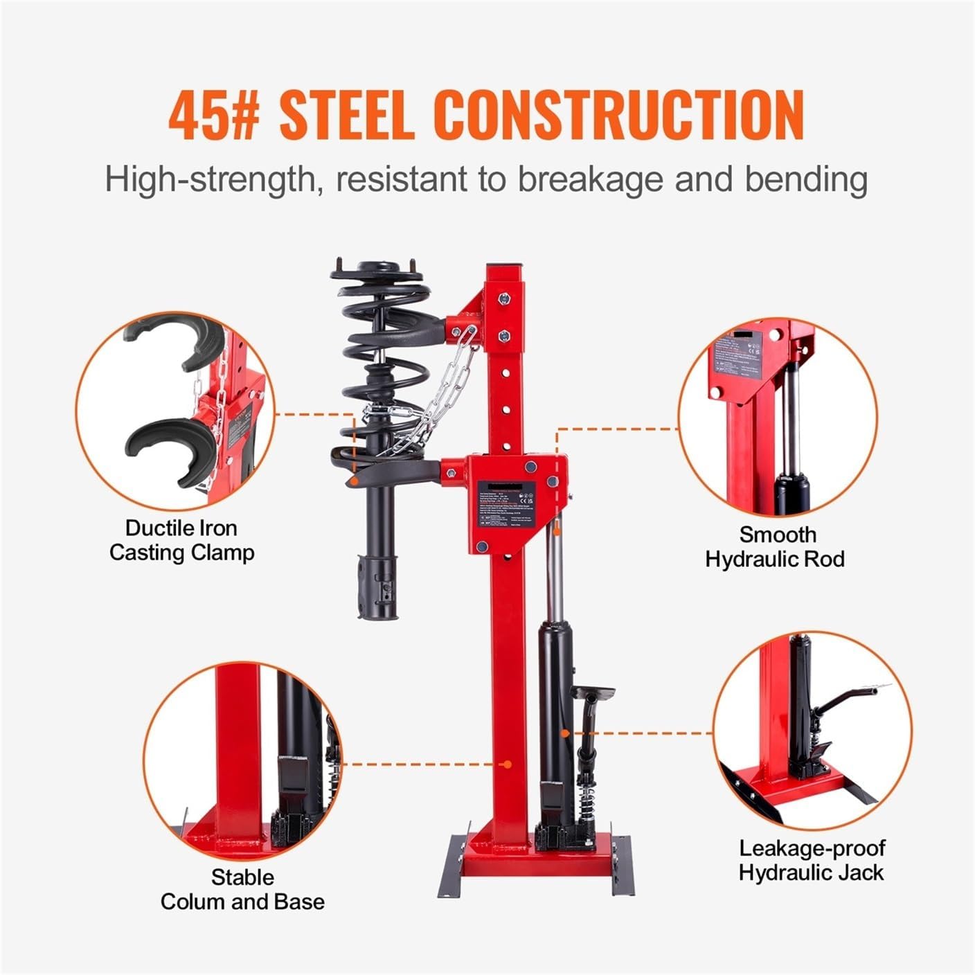
Image 3: Detailed view of the 45# steel construction. This image illustrates key components such as the ductile iron casting clamps, smooth hydraulic rod, stable column and base, and the leakage-proof hydraulic jack, emphasizing the robust build quality.
4. Setup and Assembly
The spring compressor typically comes partially assembled. Follow these steps for final setup:
- Unpack Components: Carefully remove all parts from the packaging and verify against the parts list (if provided separately).
- Position the Base: Place the H-shaped base on a firm, level, and stable surface. For enhanced safety, use appropriate fasteners to anchor the base to the ground through the pre-drilled holes.
- Attach Main Column: Ensure the main column is securely fastened to the base.
- Install Hydraulic Jack: Mount the hydraulic jack mechanism to the main column as per the design.
- Select and Install Clamps: Choose the appropriate size clamps (small for 4.3"-5.1" springs, large for 5.5"-6.7" springs) for your application. Install them onto the main column, ensuring they are securely attached and can be adjusted via the 8 positioning holes.
- Attach Safety Chain: Secure the 39.4-inch safety chain to the designated points on the compressor.
- Initial Inspection: Before first use, inspect all bolts, nuts, and connections to ensure they are tight and secure. Check the hydraulic system for any signs of leakage.

Image 4: Versatile clamping options and height adjustment. This image shows the 8 adjustment holes on the column, allowing for 2.5-inch increments in height, and illustrates the two sizes of replaceable clamps (4.3"-5.1" and 5.5"-6.7") for adapting to various spring dimensions.
5. Operating Instructions
Follow these steps to safely compress a coil spring:
- Prepare the Spring: Remove the strut assembly from the vehicle. Clean the spring and strut to ensure a clear view of all components.
- Adjust Clamp Height: Using the 8 positioning holes, adjust the upper and lower clamps to an appropriate height for the spring. Ensure the clamps are positioned to grip the spring coils securely and evenly. The maximum compression stroke is 12.6 inches (320 mm).
- Position the Spring: Carefully place the coil spring into the clamps, ensuring it is centered and seated firmly. The safety tongue on the clamps should engage to prevent accidental dislodgement.
- Engage Safety Chain: Wrap the 39.4-inch safety chain around the spring and secure it. This provides an additional layer of protection in case of clamp slippage.
- Apply Compression: Operate the hydraulic jack pedal to slowly compress the spring. Observe the spring carefully during compression to ensure it remains properly seated and does not bind. Compress only enough to allow for removal or installation of the strut components.
- Maintain Stability: The stable suspension system will hold the clamp's position when pressure stops, preventing bouncing.
- Release Pressure: Once the necessary work is completed, slowly and carefully press the second pedal (release valve) to release the hydraulic pressure. Allow the spring to decompress gradually.
- Remove Spring: Once fully decompressed, unhook the safety chain and carefully remove the spring from the clamps.

Image 5: Demonstrating maximum load capacity and compression stroke. This image shows the spring compressor in action, compressing a strut assembly, highlighting its 4.5-ton maximum load capacity and a 12.6-inch maximum compression stroke.

Image 6: Stable suspension and pressure release. This image illustrates how the clamp maintains its position when pressure is paused and shows the second pedal used to slowly release the hydraulic pressure, ensuring controlled decompression.
6. Maintenance
Regular maintenance ensures the longevity and safe operation of your spring compressor:
- Cleaning: After each use, clean the compressor to remove dirt, grease, and debris.
- Lubrication: Periodically lubricate all moving parts, including the hydraulic rod and clamp adjustment mechanisms, with a suitable lubricant.
- Inspection: Regularly inspect the entire unit for signs of wear, damage, or corrosion. Pay close attention to the clamps, safety chain, hydraulic hose (if applicable), and the base.
- Hydraulic Fluid: Check the hydraulic fluid level periodically and top up if necessary, using only recommended hydraulic fluid. Consult a qualified technician if you suspect a hydraulic leak.
- Storage: Store the compressor in a clean, dry place, away from moisture and extreme temperatures.
7. Troubleshooting
Refer to this section for common issues and their potential solutions:
| Problem | Possible Cause | Solution |
|---|---|---|
| Hydraulic jack does not lift or lifts slowly. | Low hydraulic fluid level, air in the system, or faulty pump. | Check fluid level and refill. Bleed air from the system (refer to hydraulic jack specific instructions). If problem persists, consult a technician. |
| Spring slips from clamps. | Improper seating of spring, incorrect clamp size, or worn clamps. | Ensure spring is fully seated and safety tongue is engaged. Use correct clamp size. Inspect clamps for wear and replace if necessary. Always use the safety chain. |
| Compressor wobbles during operation. | Not anchored to the ground, uneven surface, or loose connections. | Anchor the base to the ground. Ensure the compressor is on a level, stable surface. Tighten all bolts and connections. |
| Hydraulic fluid leakage. | Damaged seals or fittings. | Stop use immediately. Consult a qualified technician for repair. |
8. Specifications
| Feature | Detail |
|---|---|
| Hydraulic Load Capacity | 4.5 Ton / 9920 LBS |
| Rated Compression Force | 1 Ton |
| Small Spring Clasp Range | 4.3" to 5.1" |
| Big Spring Clasp Range | 5.5" to 6.7" |
| Maximum Compression Stroke | 12.6" / 320 mm |
| Column Adjustment Holes | 8 positions |
| Safety Chain Length | 39.4" |
| Material | Q235 Reinforced Steel (Column), Ductile Cast Iron (Clamps) |
| Manufacturer | US6AQC |
| ASIN | B0F6C61CD1 |
9. Warranty and Support
Warranty: This product comes with a 3-month warranty from the date of purchase. This warranty covers manufacturing defects under normal use. It does not cover damage resulting from misuse, abuse, unauthorized modification, or normal wear and tear.
Customer Support: For technical assistance, warranty claims, or replacement parts, please contact your retailer or the manufacturer (US6AQC) directly. Please have your product model (B0F6C61CD1) and purchase date available when contacting support.