1. Introduction
This manual provides essential information for the safe and efficient operation, installation, and maintenance of the Mechanivis AMS2106 Thermal Mass Gas Flow Meter. Please read this manual thoroughly before using the device to ensure proper functionality and safety.
Key Features:
- High Durability: Designed for long service life in demanding industrial environments.
- Strong Adaptability: Can be used in various industrial applications for gas flow measurement.
- Signal Output: Provides standard electrical or digital signals, including RS485.
- Wide Application: Utilized in industrial production, environmental protection, and energy management fields.
2. Product Overview
The Mechanivis AMS2106 is a thermal mass gas flow meter engineered for precise measurement of various gases, including Air, N2, O2, CO2, and Ar. It features a clear digital segment code screen for real-time display and RS485 communication for seamless integration into control systems.
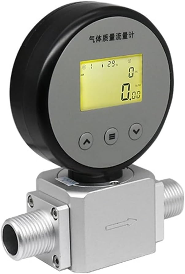
Figure 1: Front view of the AMS2106 Flow Meter.
Components:
- Flow Meter Body (Constructed from 6061 Aluminium alloy)
- Digital Segment Code Display Screen
- Control Buttons (Up, Menu, Down) for navigation and settings
- Gas Inlet/Outlet Ports (Available in NPT 3/8 or NPT 1/2 depending on the specific variant)
- Type-C Port for power and data connection

Figure 2: Side view showing the Type-C port.
3. Setup and Installation
3.1 Unpacking and Inspection
Carefully unpack the flow meter and inspect it for any signs of damage during transit. Ensure all listed components are present. The package should contain one flow meter unit. If any damage or missing parts are found, contact your supplier immediately.
3.2 Mounting
The AMS2106 is designed for inline installation within your gas piping system. It is crucial to ensure the flow direction arrow, clearly marked on the meter body, aligns with the actual gas flow in your system. Mount the meter securely to a stable structure to prevent vibration, which could affect measurement accuracy.
3.3 Electrical Connection
The device can be powered by an external 9-24V DC source or internal batteries. Connect the appropriate power supply using the Type-C port. For digital communication with a control system, connect the RS485 interface according to your system's wiring diagram. Ensure all electrical connections are secure and comply with local electrical codes.
3.4 Gas Connection
Connect the gas lines to the inlet and outlet ports of the flow meter. Use appropriate sealing materials (e.g., PTFE tape) to ensure all connections are leak-free. The meter is calibrated for specific gases (Air, N2, O2, CO2, Ar); ensure the gas being measured matches the meter's calibration to obtain accurate readings.
4. Operating Instructions
4.1 Power On/Off
To power on the device, ensure it is connected to a stable power source or has sufficiently charged internal batteries. The digital display will illuminate, indicating the device is active. To power off, disconnect the external power source or allow the internal batteries to deplete.
4.2 Display Readings
The segment code screen displays both the instantaneous gas flow rate and the cumulative total flow. Use the navigation buttons (Up, Menu, Down) located on the front panel to cycle through different display modes, view various parameters, or access the settings menu.
4.3 Basic Operation
Once powered on and gas flow is established through the system, the meter will automatically begin measuring. The instantaneous flow rate will be shown on the primary display, and the cumulative flow will continuously increment. For advanced configurations, such as selecting measurement units, setting alarms, or resetting cumulative values, refer to the detailed settings menu accessible via the 'Menu' button.
5. Maintenance
5.1 Cleaning
Keep the exterior of the flow meter clean by wiping it with a soft, dry cloth. Do not use abrasive cleaners, solvents, or harsh chemicals, as these can damage the housing or display. Ensure the display screen remains free from dust and smudges for clear visibility of readings.
5.2 Sensor Care
The thermal mass sensor is a delicate component critical for accurate measurements. Avoid introducing contaminants, such as oil, moisture, or particulate matter, into the gas stream. Regular inspection of the gas lines and filters (if installed) for cleanliness is recommended to prevent sensor fouling.
5.3 Battery Replacement
If operating the device using internal batteries, replace them promptly when the low battery indicator appears on the display. Refer to the battery compartment cover for the correct battery type and ensure proper polarity during installation. Always dispose of used batteries according to local regulations.
6. Troubleshooting
6.1 No Display
- Check Power Supply: Verify that the external power supply is connected correctly and providing the specified voltage (9-24V DC).
- Check Batteries: If using internal batteries, ensure they are correctly installed and sufficiently charged. Replace if necessary.
6.2 Inaccurate Readings
- Verify Gas Type: Confirm that the gas being measured matches the meter's calibration. Using the wrong gas type will result in incorrect readings.
- Check for Leaks: Inspect all gas connections for leaks, which can affect flow measurement.
- Flow Direction: Ensure the meter is installed with the flow direction arrow aligned with the actual gas flow.
- Environmental Conditions: Confirm that the operating temperature and pressure are within the specified limits (-10°C to +60°C, ≤0.8 MPa).
6.3 No Flow Detected
- Gas Supply: Ensure that gas is actively flowing through your system.
- Blockages: Check for any blockages or obstructions in the gas lines leading to or from the flow meter.
- Installation: Verify that the meter is correctly installed in the flow path and that valves are open.
7. Specifications

Figure 3: General Specifications Table for AMS Series.

Figure 4: Detailed AMS2106 Series Specifications.
| Parameter | Value |
|---|---|
| Model | AMS2106 (Air O2 N2 0.05-50L) |
| Measuring Principle | Thermal Mass Flow |
| Measuring Medium | Air, N2, O2, CO2, Ar |
| Range (Current Model) | 0.05 - 50 L/min |
| Accuracy | ±3% F.S. |
| Repeatability | 0.5% F.S. |
| Response Time | ≤2s |
| Max Pressure | ≤0.8 MPa |
| Power Supply | Battery or External 9-24V DC |
| Power Dissipation | 50mW (battery) |
| Display | Segment Code Screen |
| Communication Interface | RS485 |
| Communication Protocol | MODBUS-RTU |
| Operating Temperature | -10°C to +60°C |
| Pipe Material | 6061 Aluminium alloy |
| Connection Piping | NPT 3/8, NPT 1/2 (depending on specific variant) |
| Dimensions (L×W×H) | 89 × 42 × 124.2 mm |
| Item Weight | 6.61 pounds (approx. 3 kg) |
| Assembly Required | No |
8. Safety Information
- Always ensure proper ventilation when working with gases, especially in enclosed spaces.
- Do not exceed the maximum pressure rating of 0.8 MPa to prevent damage to the device and potential hazards.
- Ensure all electrical connections are secure, properly insulated, and meet local safety standards to avoid electrical shock.
- Avoid exposing the device to extreme temperatures, high humidity, or corrosive environments outside its specified operating range (-10°C to +60°C).
- Only qualified and trained personnel should perform installation, maintenance, and troubleshooting procedures.
- Do not attempt to modify or repair the device yourself. Refer all servicing to authorized personnel.
9. Warranty and Support
For detailed warranty information and technical support, please contact Mechanivis customer service or your authorized distributor. It is recommended to keep your purchase receipt as proof of purchase for any warranty claims. Specific warranty terms and conditions may vary by region and retailer.
For further assistance, product updates, or to access additional resources, please visit the official Mechanivis website or contact your local support representative.