1. Introduction
The YedaHcy IBT 4 Motor Driver Controller is a single-channel Pulse Width Modulation (PWM) module board designed for efficient control of DC motors. Constructed with high-quality PCB material, this driver offers high-speed switching and low heat generation, making it suitable for a variety of applications.
Application Scope: This motor driver is ideal for use in robots, smart cars, hollow cup motors, DC brush motors, semiconductor refrigeration systems, and various industrial control applications.
2. Product Features
- Durable Construction: Manufactured with high-quality PCB material for enhanced reliability, miniaturization, and ease of maintenance.
- Broad Compatibility: Suitable for a wide range of applications including smart car motor drives, control board extensions, and semiconductor refrigeration.
- Efficient Performance: Engineered for high-speed switching and ultra-low internal resistance, ensuring efficient operation and reduced heat.
- Flexible Control: Supports both Clockwise (CW) and Counter-Clockwise (CCW) directional control, along with PWM for precise speed regulation of various motors.
3. Package Contents
- 1 x YedaHcy IBT 4 Motor Driver Controller
4. Technical Specifications
| Parameter | Value |
|---|---|
| Rated Voltage | 5V~12V/DC (14.6V Maximum, limit voltage) |
| Working Current | 0A~50A (maximum) |
| PWM Control Mode Duty Cycle | 0%~98% |
| Recommended PWM Frequency (Ordinary Motor) | 16kHz |
| Recommended PWM Frequency (Hollow Cup Motor) | 80kHz |
| Recommended PWM Frequency (Semiconductor Refrigeration) | 500Hz~80kHz |
| Input Level Voltage (Low) | 0V~0.5V |
| Input Level Voltage (High) | 2.5V~13V (compatible with typical 3.3V, 5V, 12V levels) |
| Item Weight | 1.06 ounces |
| Package Dimensions | 2.36 x 1.97 x 1.18 inches |
| Model Number | YedaHcyop80xseth3 |
| ASIN | B0F636TDS3 |
5. Setup and Connections
This section details the physical connections required to operate your IBT 4 Motor Driver Controller.

Figure 5.1: Overall view of the IBT 4 Motor Driver Controller, showing the heatsink, input pins, and motor power terminals.
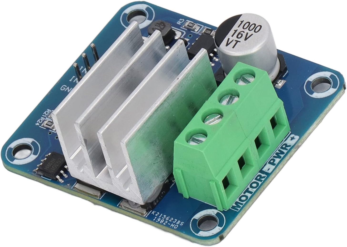
Figure 5.2: Detailed view of the control input pins (IN1, IN2, GND) and the motor power terminals (MOTOR-PWR +/-).
5.1. Power Connections
- Connect your DC motor's power supply to the large green screw terminals labeled MOTOR-PWR + and MOTOR-PWR -. Ensure correct polarity. The rated voltage for the motor power supply is 5V to 12V DC, with a maximum limit of 14.6V.
- The driver board itself draws power from these terminals.
5.2. Control Signal Connections
- Connect your control signals (e.g., from a microcontroller) to the yellow header pins labeled IN1, IN2, and GND.
- IN1 and IN2 are used for directional control and PWM input.
- GND is the common ground connection for the control signals.
- The input level voltage for control signals can be 0V-0.5V for low and 2.5V-13V for high, compatible with 3.3V, 5V, and 12V logic levels.
6. Operating Instructions
The IBT 4 Motor Driver Controller allows for precise control over DC motors using PWM signals.
6.1. Directional Control (CW/CCW)
Motor direction is controlled by the logic states of the IN1 and IN2 pins. Typically:
- To drive the motor in one direction (e.g., Clockwise): Set IN1 HIGH, IN2 LOW.
- To drive the motor in the opposite direction (e.g., Counter-Clockwise): Set IN1 LOW, IN2 HIGH.
- To stop the motor: Set both IN1 and IN2 LOW, or both HIGH (depending on specific motor and driver configuration, typically both LOW for brake/coast).
6.2. Speed Control (PWM)
Motor speed is controlled by applying a PWM signal to one of the input pins (e.g., IN1) while the other pin (IN2) is held at a fixed logic level (HIGH or LOW) to determine direction. The duty cycle of the PWM signal directly correlates to the motor's speed.
- Duty Cycle: The PWM duty cycle can range from 0% (motor off) to 98% (maximum speed).
- PWM Frequency: The optimal PWM frequency depends on the type of motor being controlled. Refer to the recommended frequencies in the Technical Specifications section (Section 4).
7. Important Notes and Warnings
- The input PWM duty cycle must not exceed 98%. Exceeding this value may lead to unstable operation or permanent damage to the driver.
- The selection of PWM frequency is critical and depends on the load type. When possible, use the recommended frequency values provided in the specifications or an approximate value.
- Ensure all power and control connections are secure and correctly polarized before applying power to prevent damage to the driver or connected components.
8. Troubleshooting
If you encounter issues with your IBT 4 Motor Driver Controller, consider the following:
- Motor Not Responding: Verify all power connections to the motor and the driver board. Check control signal connections (IN1, IN2, GND) for proper wiring and logic levels. Ensure the motor power supply is within the rated voltage range.
- Motor Runs Erratically: Check the PWM signal's duty cycle and frequency. Ensure they are within the specified limits and recommended values for your motor type. Inspect for loose connections or intermittent signals.
- Driver Overheating: Ensure the motor current does not exceed the maximum working current of 50A. Verify that the heatsink is properly installed and has adequate airflow. Reduce load or operating time if continuous overheating occurs.
- Incorrect Direction: Review the logic states applied to IN1 and IN2. Swap the motor's power leads if the direction is consistently inverted and control signals are correct.
9. Maintenance
The IBT 4 Motor Driver Controller is designed for reliable operation with minimal maintenance. To ensure longevity:
- Keep the board clean and free from dust and debris. Use a soft, dry brush or compressed air for cleaning.
- Avoid exposing the board to moisture or extreme temperatures.
- Periodically check all connections for tightness, especially in high-vibration environments.
10. Warranty and Support
For warranty information or technical support regarding your YedaHcy IBT 4 Motor Driver Controller, please refer to the documentation provided at the point of purchase or contact your vendor directly. Keep your purchase receipt for warranty claims.