1. Introduction
This manual provides comprehensive instructions for the safe and effective use of the Generic 5-90V DC Digital Automotive Circuit Tester. This versatile tool is designed for precise voltage detection, continuity testing, and fuse diagnostics in various automotive and marine electrical systems.
Key Features:
- Precise Voltage Detection: Accurately displays voltage readings from 5V to 90V DC, suitable for automotive, RV, and fuse testing.
- Durable Design with LED Indicator: Equipped with a high-brightness LED indicator, stainless steel probes, and an extended spring-loaded cable for durability and access in confined areas.
- Multi-Functional Use: Functions as a circuit tester, voltage detector, and fuse tester for various vehicles including cars, trucks, and marine vessels.
- Safe and User-Friendly: Designed with a clear digital display and ergonomic grip for convenient operation.
- Included Accessories: Comes with sturdy probes and connecting cables, compatible with 12V/24V systems for automotive electrical inspections and DIY projects.
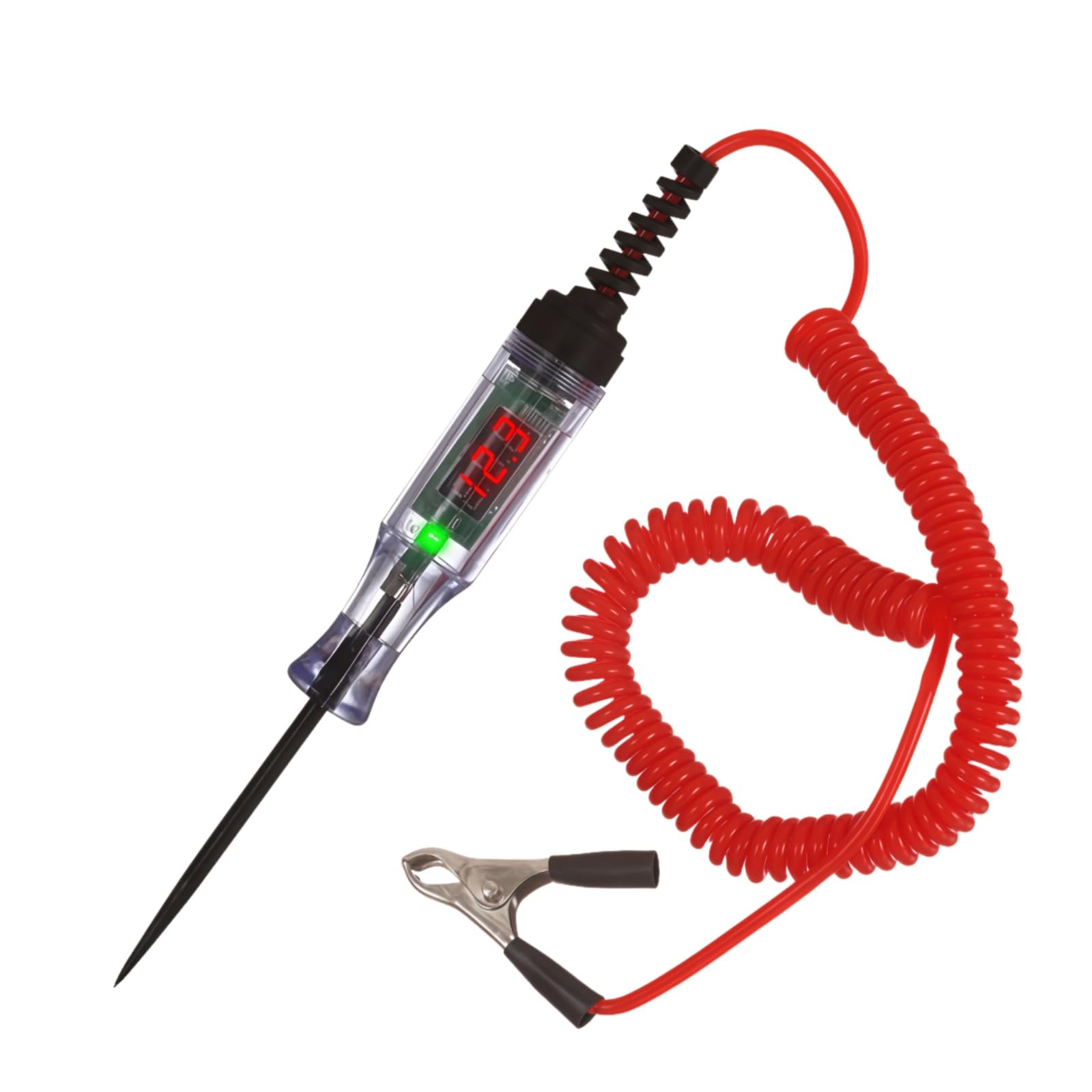
Figure 1.1: Generic 5-90V DC Digital Automotive Circuit Tester.
2. Safety Information
Always observe the following safety precautions to prevent injury or damage to the device or vehicle:
- Wear appropriate personal protective equipment, including safety glasses.
- Do not use the tester on circuits exceeding 90V DC.
- Ensure proper grounding of the alligator clip before probing live circuits.
- Keep the probe tip away from moving parts or hot surfaces.
- Do not attempt to repair or modify the tester. Refer to qualified personnel for service.
3. Product Components
The Automotive Circuit Tester consists of the following main components:
- Digital Display: Shows voltage readings.
- LED Indicator: Provides visual feedback on circuit status.
- Stainless Steel Probe: Sharp tip for piercing wires or contacting terminals.
- Extended Spring Wire: Flexible coiled cable for reach and tangle-free use.
- Alligator Clip: For secure connection to ground or power sources.

Figure 3.1: Labeled components of the Automotive Circuit Tester, including the LED digital display, indicator light, probe, alligator clips, and extended spring wire.

Figure 3.2: Dimensions of the Automotive Circuit Tester, showing the probe length (7.24 inches), overall length (9.6 inches), and alligator clip length (2.08 inches).
4. Setup
- Connect the Alligator Clip: Securely attach the alligator clip to a known good ground point on the vehicle chassis or the negative terminal of the battery. Ensure a clean, solid connection for accurate readings.
- Prepare the Probe: Remove the protective cover from the stainless steel probe tip.
5. Operating Instructions
5.1. Voltage Testing
- Ensure the alligator clip is securely grounded.
- Carefully touch the probe tip to the circuit or component you wish to test.
- The digital display will show the voltage reading. The LED indicator will illuminate (red for positive, green for negative) to indicate polarity.
- If the voltage exceeds the tester's maximum capacity (90V DC), the display may show an error or an "H" indicating high voltage. Disconnect immediately.
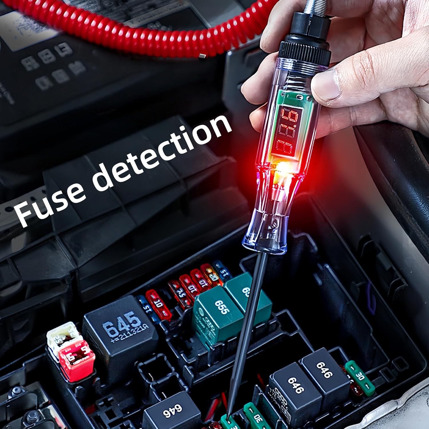
Figure 5.1: The circuit tester in use, demonstrating fuse detection within a vehicle's fuse box.
Video 5.1: Demonstration of DC voltage testing and resistance testing using a similar automotive circuit tester. Note: The voltage range shown in this video may differ from the 5-90V range of this product.
Video 5.2: Demonstration of voltage testing and continuity testing with an automotive test light. Note: The voltage range shown in this video may differ from the 5-90V range of this product.
5.2. Continuity Testing
- Ensure the circuit is de-energized before performing continuity tests.
- Connect the alligator clip to one end of the component or wire to be tested.
- Touch the probe tip to the other end.
- If continuity exists, the LED indicator will light up (typically green for continuity, or red if connected to a positive source through the component) and the display may show a low resistance value or a specific continuity symbol.
Video 5.3: Demonstration of polarity detection and continuity testing using a power circuit probe tester. Note: The voltage range shown in this video may differ from the 5-90V range of this product.
5.3. Fuse Testing
- With the circuit energized, connect the alligator clip to a known good ground.
- Touch the probe tip to each test point on the top of the fuse.
- If both sides of the fuse show a voltage reading, the fuse is good. If one side shows voltage and the other does not, the fuse is blown.

Figure 5.2: The Automotive Circuit Tester is suitable for use with motorcycles, heavy equipment, trucks, and cars.
6. Maintenance
- Cleaning: Wipe the tester with a clean, dry cloth after each use. Do not use abrasive cleaners or solvents.
- Storage: Store the tester in a dry, cool place, away from direct sunlight and extreme temperatures. Always replace the protective probe cover before storage.
- Cable Inspection: Regularly inspect the spring wire and alligator clip for any signs of damage, fraying, or corrosion. Replace if necessary.
7. Troubleshooting
| Problem | Possible Cause | Solution |
|---|---|---|
| No display/LED light | Poor ground connection; No power in circuit; Faulty tester. | Ensure alligator clip has a solid ground. Verify circuit has power. Test tester on a known live circuit. |
| Inaccurate voltage reading | Poor connection; High resistance in circuit. | Clean connection points. Ensure firm contact with probe. |
| "H" or error message on display | Voltage exceeds 90V DC. | Immediately disconnect the tester. This tester is not designed for voltages above 90V DC. |
8. Specifications
| Feature | Detail |
|---|---|
| Model Number | 605195370602 (DYB-002) |
| Voltage Range | 5-90V DC |
| Display Type | Digital LED |
| Probe Material | Stainless Steel |
| Cable Type | Extended Spring Wire |
| Cable Length | Approx. 96 inches (244 cm) |
| Product Dimensions (L x W x H) | 18.42 x 2.01 x 2.01 cm (7.25 x 0.79 x 0.79 inches) |
| Item Weight | 90 g |
| Power Source | Powered by circuit under test |
| Manufacturer | JINJIANG |
| Certifications | CE, ETL |
9. Warranty and Support
For warranty information or technical support, please refer to the retailer or manufacturer's official website. Keep your purchase receipt for warranty claims.