
1. Introduction and Overview
This manual provides essential information for the proper installation, operation, and maintenance of the FCGBZHRL AC2000 B220502000001 Governor Accelerator. This component is designed to precisely control engine speed in compatible heavy machinery, specifically XCMG XE210 and SANY SY155-8, SY205-8, SY205C, SY210C-8, SY215-8, SY235-8 Excavators. Adherence to these instructions will ensure optimal performance and longevity of the unit.
2. Safety Information
Always prioritize safety during installation, operation, and maintenance. Failure to follow safety guidelines can result in serious injury or damage to equipment.
- Professional Installation: Installation should only be performed by qualified personnel with experience in heavy machinery electrical and mechanical systems.
- Disconnect Power: Before beginning any installation or maintenance, ensure the excavator's battery is disconnected to prevent accidental startup or electrical shock.
- Wear Personal Protective Equipment (PPE): Always wear appropriate PPE, including safety glasses, gloves, and protective footwear.
- Secure Components: Ensure all connections are secure and all components are properly mounted to prevent vibration damage or dislodgement during operation.
- Check for Obstructions: Verify that cables and moving parts are clear of any potential pinch points or areas of friction.
3. Product Components
The AC2000 B220502000001 Governor Accelerator typically includes the main control module, electrical wiring harness, and the accelerator cable assembly.

Figure 3.1: Overall view of the Governor Accelerator, showing the central control module, the attached electrical harness with its connector, and the long accelerator cable that connects to the engine's throttle mechanism.

Figure 3.2: A closer look at the main control module from the top, highlighting the robust metal casing, the two bolts for secure mounting, and the multi-pin electrical connector for power and signal input.

Figure 3.3: Rear perspective of the governor accelerator module, revealing the cable entry points into the module and the integrated mounting bracket designed for secure attachment within the excavator's engine compartment.
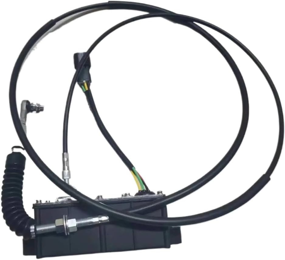
Figure 3.4: Side view illustrating the compact design of the governor accelerator module and the robust, flexible conduit protecting the accelerator cable, ensuring durability in demanding environments.
4. Setup and Installation
Follow these steps carefully for proper installation of the governor accelerator.
- Preparation:
- Ensure the excavator is turned off and the battery is disconnected.
- Locate the mounting area for the new governor accelerator, typically near the engine's throttle body or existing governor.
- Remove the old governor accelerator if replacing an existing unit.
- Mounting the Module:
- Securely mount the AC2000 B220502000001 module using appropriate bolts and washers to a stable surface, ensuring it is free from excessive vibration and heat.
- Verify that the module's position allows for proper routing of both the electrical harness and the accelerator cable without sharp bends or strain.
- Connecting the Electrical Harness:
- Connect the electrical harness from the new governor accelerator to the corresponding connector on the excavator's wiring system. Ensure the connection is firm and latched.
- Inspect the wiring for any signs of damage or corrosion before connecting.
- Connecting the Accelerator Cable:
- Route the accelerator cable from the module to the engine's throttle mechanism. Ensure the cable path is clear of moving parts and heat sources.
- Connect the end of the accelerator cable to the throttle lever or linkage according to the excavator's service manual.
- Adjust the cable tension as necessary to ensure full range of motion for the throttle without binding or excessive slack.
- Post-Installation Checks:
- Reconnect the excavator's battery.
- Start the engine and perform a functional test to ensure the governor accelerator responds correctly to input and maintains stable engine speed.
- Check for any error codes or abnormal operation.
5. Operating Instructions
The AC2000 B220502000001 Governor Accelerator is an integral control unit designed to automatically regulate the engine speed of your excavator based on operator input and system demands. Once correctly installed, its operation is seamless and integrated with the excavator's existing control system.
- Automatic Control: The unit receives signals from the excavator's control system (e.g., joystick, pedal input) and translates them into precise mechanical adjustments of the engine's throttle via the accelerator cable.
- Engine Speed Regulation: It ensures the engine maintains the desired RPM under varying loads, optimizing fuel efficiency and power delivery for different operational tasks.
- No User Adjustment: This component is a direct replacement part and does not typically require user adjustments or calibration after proper installation. Any calibration or fine-tuning should be performed through the excavator's main control system diagnostics, if applicable.
6. Maintenance
Regular inspection and basic maintenance will help ensure the longevity and reliable performance of your governor accelerator.
- Visual Inspection (Monthly/Per Service Interval):
- Check all electrical connections for tightness and signs of corrosion. Clean if necessary.
- Inspect the accelerator cable for fraying, kinks, or damage to the outer casing. Ensure it moves freely without binding.
- Verify that the module is securely mounted and that mounting bolts are tight.
- Look for any signs of physical damage to the module casing.
- Cleaning:
- Keep the module and cable free from excessive dirt, grease, and debris. Use a clean, damp cloth to wipe down surfaces. Avoid using harsh chemicals or high-pressure water directly on the unit.
- Lubrication:
- Periodically apply a small amount of appropriate lubricant to the moving parts of the accelerator cable at the throttle linkage end, as recommended by the excavator's manufacturer.
7. Troubleshooting
If you experience issues with engine speed control, perform the following basic troubleshooting steps. For complex issues, consult a qualified technician.
- Engine Speed Erratic or Unresponsive:
- Check Electrical Connections: Ensure all electrical connectors to the governor accelerator module are clean, secure, and free from corrosion.
- Inspect Accelerator Cable: Verify the accelerator cable is not kinked, frayed, or binding. Ensure it moves freely from the module to the throttle linkage.
- Power Supply: Confirm that the module is receiving proper power from the excavator's electrical system.
- Engine Idles Too High/Low:
- Cable Adjustment: Re-check the tension and adjustment of the accelerator cable at the throttle linkage. It should allow for full throttle range without being too tight or too loose at idle.
- System Calibration: If the issue persists, the excavator's main control system may require recalibration or diagnosis by a specialized technician.
- No Movement from Accelerator Cable:
- Module Power: Confirm the module is powered.
- Internal Fault: If power is present and the cable is free, the module may have an internal fault and require replacement.
Note: This governor accelerator is a precision component. Do not attempt to disassemble the module. Contact a certified technician or the manufacturer for advanced diagnostics and repairs.
8. Specifications
| Attribute | Value |
|---|---|
| Model Number | AC2000 B220502000001 |
| Brand | FCGBZHRL |
| Compatible Excavators | XCMG XE210, SANY SY155-8, SY205-8, SY205C, SY210C-8, SY215-8, SY235-8 |
| Package Dimensions | 1.18 x 1.18 x 1.18 inches |
| Item Weight | 7 ounces |
| Manufacturer | FCGBZHRL |
| ASIN | B0F62QCGPW |
| UPC | 761946478680 |
9. Warranty and Support
For specific warranty terms and conditions, please refer to the documentation provided at the time of purchase or contact your seller directly. Warranty coverage typically applies to manufacturing defects and does not cover damage resulting from improper installation, misuse, or normal wear and tear.
For technical support, troubleshooting assistance beyond this manual, or to inquire about replacement parts, please contact the manufacturer or your authorized distributor. When contacting support, please have your product model number (AC2000 B220502000001) and purchase information readily available.
Manufacturer: FCGBZHRL