
1. Introduction
This manual provides essential information for the safe and effective use of your Thsinde TRMS 6000 Auto Ranging Digital Multimeter. Please read it thoroughly before operation and retain it for future reference. This device is designed for measuring AC/DC voltage, AC/DC current, resistance, capacitance, frequency, diode, and continuity, and features Non-Contact Voltage (NCV) detection.

Figure 1: Thsinde TRMS 6000 Digital Multimeter. This image displays the front view of the multimeter, highlighting its large LCD screen and rotary function switch.
2. Safety Information
WARNING: To avoid possible electric shock, fire, or personal injury, please read all safety information before using the product.
- Always ensure the multimeter is in good working condition and that the test leads are not damaged.
- Do not apply more than the rated voltage, as marked on the meter, between the terminals or between any terminal and earth ground.
- Use caution when working with voltages above 30V AC RMS, 42V peak, or 60V DC. These voltages pose a shock hazard.
- Always disconnect the test leads from the circuit before changing functions.
- Do not use the meter if the battery cover is not properly closed.
- Replace the battery as soon as the low battery indicator appears to ensure accurate readings.
- Adhere to local and national safety codes.
3. Package Contents
Verify that all items listed below are included in your package:
- Thsinde TRMS 6000 Digital Multimeter
- 9V Battery
- English User's Manual (this document)
- 2 x Test Leads (one red, one black)
- 2 x Alligator Clips (one red, one black)

Figure 2: Multimeter with included test leads and alligator clips. This image shows the multimeter connected to its red and black test leads, which are further connected to red and black alligator clips, illustrating the complete set of accessories.
4. Product Overview
Familiarize yourself with the components of your digital multimeter:
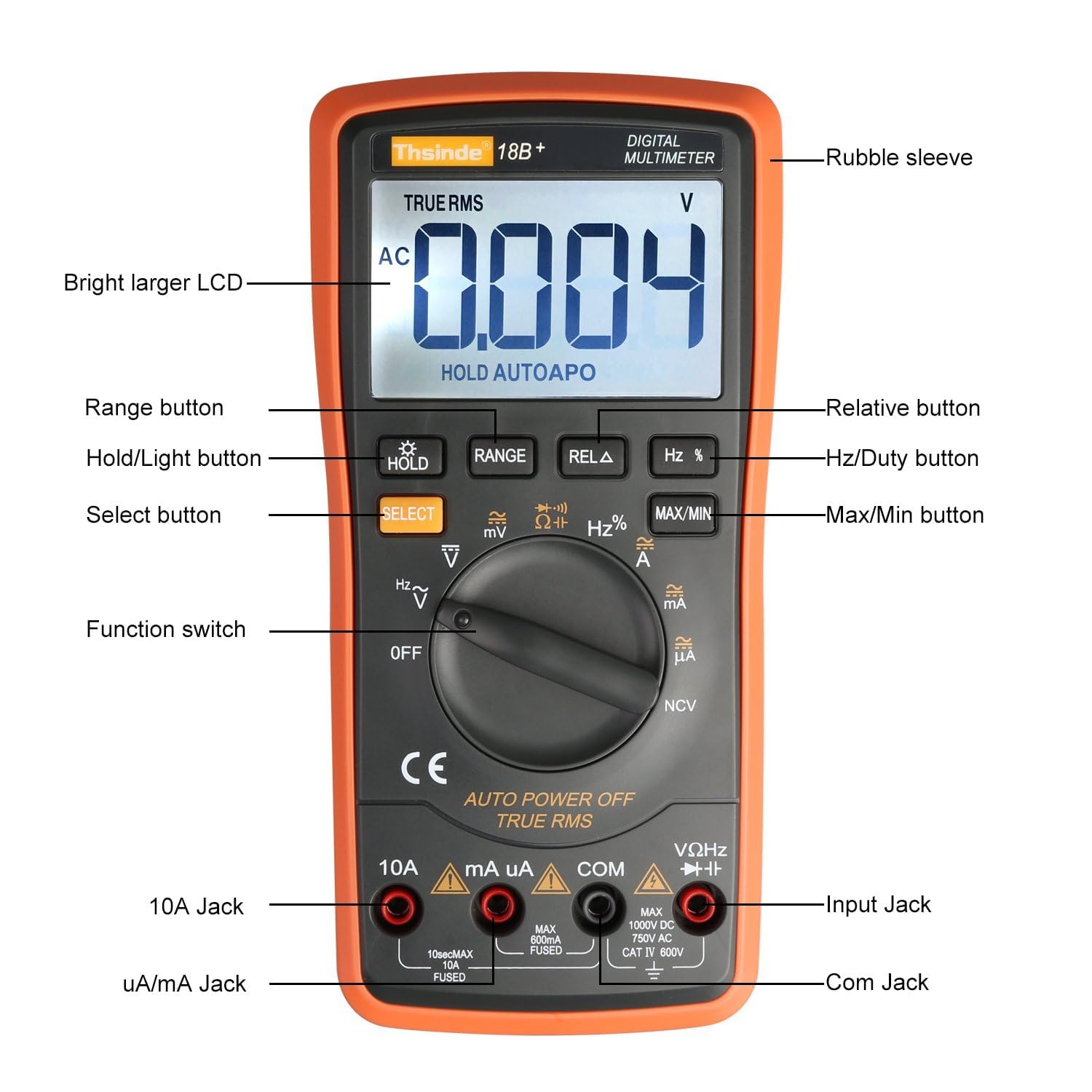
Figure 3: Labeled diagram of the Thsinde TRMS 6000 Multimeter. This image provides a detailed view of the multimeter with labels pointing to its key components, including the LCD, buttons, function switch, and input jacks.
- Rubble sleeve: Protective outer casing.
- Bright larger LCD: Digital display for readings.
- Range button: Manually selects measurement range (if not in auto-ranging mode).
- Hold/Light button: Freezes the current reading on the display; long press activates/deactivates backlight.
- Select button: Toggles between different functions within a single rotary switch position (e.g., AC/DC, Diode/Continuity).
- Function switch: Rotary switch to select the desired measurement function.
- 10A Jack: Input terminal for high current (up to 10A) measurements.
- uA/mA Jack: Input terminal for microampere and milliampere current measurements.
- COM Jack: Common (negative) input terminal for all measurements.
- Input Jack (VΩHz): Positive input terminal for voltage, resistance, frequency, capacitance, diode, and continuity measurements.
- Max/Min button: Displays maximum or minimum recorded values during a measurement session.
- Hz/Duty button: Toggles between frequency and duty cycle measurements.
- Relative button: Stores the current reading as a reference value and displays subsequent readings as a deviation from this reference.
5. Setup
5.1 Battery Installation
The multimeter requires one 9V battery for operation. To install or replace the battery:
- Ensure the multimeter is turned OFF.
- Locate the battery compartment on the back of the multimeter.
- Use a screwdriver to remove the screw securing the battery cover.
- Carefully remove the battery cover.
- Connect the 9V battery to the battery clips, observing correct polarity (+ to + and - to -). The positive terminal is typically on the left when viewing from the rear.
- Place the battery into the compartment, ensuring it fits snugly.
- Replace the battery cover and secure it with the screw.
5.2 Connecting Test Leads
Always connect the black test lead to the COM jack. Connect the red test lead to the appropriate input jack based on the measurement type:
- For Voltage, Resistance, Frequency, Capacitance, Diode, and Continuity measurements: Connect the red lead to the VΩHz jack.
- For microampere (µA) or milliampere (mA) current measurements: Connect the red lead to the uA/mA jack.
- For high current (up to 10A) measurements: Connect the red lead to the 10A jack.
6. Operating Instructions
6.1 Basic Operation
- Turn the function switch to the desired measurement function.
- Connect the test leads to the circuit or component under test.
- Read the measurement value on the LCD.
- To turn off the multimeter, rotate the function switch to the OFF position.
6.2 Auto Ranging
The TRMS 6000 features auto-ranging, which automatically selects the appropriate measurement range for the input signal. This simplifies operation as you do not need to manually select a range. If manual ranging is desired for specific functions, press the RANGE button.
6.3 Data Hold
Press the HOLD button to freeze the current reading on the display. Press it again to release the hold function and resume live readings.
6.4 Backlight
Long press the HOLD/Light button to activate or deactivate the LCD backlight. This feature is useful for working in dimly lit environments.

Figure 4: Multimeter display with backlight activated in a dark setting. This image demonstrates the clear visibility of the LCD readings even in low-light conditions, thanks to the integrated backlight.
6.5 Auto Power Off (APO)
The multimeter will automatically power off after approximately 15 minutes of inactivity to conserve battery life. To disable or re-enable APO, refer to the detailed user manual for specific button combinations during power-on.
7. Measurement Functions
The Thsinde TRMS 6000 offers a variety of measurement functions:

Figure 5: Icons representing various multimeter functions. This image displays a visual guide to the different measurement capabilities of the multimeter, such as Diode test, Frequency, Backlight, True RMS, Electric resistance, Max/Min value, Data hold, LCD display, Range, Auto Power Off, and Select.
7.1 DC Voltage Measurement (V DC)
- Turn the function switch to the V position. If necessary, press SELECT to choose DC voltage.
- Connect the black test lead to COM and the red test lead to VΩHz.
- Connect the test leads in parallel to the circuit or component.
- Range and Accuracy: 600mV, 6V, 60V, 600V ±(0.5%+3); 1000V ±(0.8%+10).
7.2 AC Voltage Measurement (V AC)
- Turn the function switch to the V position. If necessary, press SELECT to choose AC voltage.
- Connect the black test lead to COM and the red test lead to VΩHz.
- Connect the test leads in parallel to the circuit or component.
- Range and Accuracy: 6V, 60V, 600V ±(0.8%+5); 750V ±(1.2%+10).
7.3 DC Current Measurement (A DC)
- Turn the function switch to the A or mA/µA position. If necessary, press SELECT to choose DC current.
- For µA/mA: Connect the black test lead to COM and the red test lead to uA/mA.
- For 10A: Connect the black test lead to COM and the red test lead to 10A.
- Connect the test leads in series with the circuit.
- Range and Accuracy: 600µA, 6000µA ±(0.8%+3); 60mA, 600mA, 10A ±(2%+30).
7.4 AC Current Measurement (A AC)
- Turn the function switch to the A or mA/µA position. If necessary, press SELECT to choose AC current.
- For µA/mA: Connect the black test lead to COM and the red test lead to uA/mA.
- For 10A: Connect the black test lead to COM and the red test lead to 10A.
- Connect the test leads in series with the circuit.
- Range and Accuracy: 600µA, 6000µA ±(0.8%+10); 60mA, 600mA, 10A ±(2%+30).
7.5 Resistance Measurement (Ω)
- Turn the function switch to the Ω position.
- Connect the black test lead to COM and the red test lead to VΩHz.
- Connect the test leads across the component. Ensure the circuit is de-energized.
- Range and Accuracy: 600Ω ±(0.8%+5); 6KΩ, 60KΩ, 600KΩ, 6MΩ ±(0.8%+3); 60MΩ ±(1%+25).
7.6 Capacitance Measurement (F)
- Turn the function switch to the Capacitance position (often shared with Diode/Continuity, use SELECT).
- Connect the black test lead to COM and the red test lead to VΩHz.
- Connect the test leads across the capacitor. Ensure the capacitor is discharged before testing.
- Range and Accuracy: 60nF, 600nF, 6µF, 60µF ±(3.5%+20); 600µF, 6000µF ±(5.0%+10).
7.7 Frequency Measurement (Hz)
- Turn the function switch to the Hz position (often shared with voltage, use SELECT).
- Connect the black test lead to COM and the red test lead to VΩHz.
- Connect the test leads to the signal source.
- Range and Accuracy: 10Hz to 20MHz ±(0.1%+3).
7.8 Diode Test
- Turn the function switch to the Diode position (often shared with Continuity, use SELECT).
- Connect the black test lead to COM and the red test lead to VΩHz.
- Connect the red lead to the anode and the black lead to the cathode of the diode. A forward voltage drop will be displayed. Reverse the leads; the display should show OL (Open Loop).
7.9 Continuity Test
- Turn the function switch to the Continuity position (often shared with Diode, use SELECT).
- Connect the black test lead to COM and the red test lead to VΩHz.
- Connect the test leads across the circuit or component. If resistance is below approximately 50Ω, the buzzer will sound, indicating continuity.
7.10 Non-Contact Voltage (NCV) Detection
- Turn the function switch to the NCV position.
- Move the top end of the multimeter near a conductor.
- If AC voltage is detected (typically above 700V RMS), the instrument sensor will light up and an audible buzz will be emitted.

Figure 6: Multimeter demonstrating Non-Contact Voltage (NCV) detection. This image shows the multimeter held near a power strip, indicating its ability to detect AC voltage without direct contact, accompanied by an alarm sound icon.
8. Maintenance
8.1 Cleaning
Wipe the case with a damp cloth and a mild detergent. Do not use abrasives or solvents. Ensure the multimeter is completely dry before use.
8.2 Battery Replacement
When the low battery indicator appears on the display, replace the 9V battery as described in Section 5.1. Prompt battery replacement ensures continued accuracy and proper operation.
9. Troubleshooting
- No display or faint display: Check battery installation and replace the 9V battery if necessary.
- Incorrect readings: Ensure test leads are correctly connected to the appropriate jacks for the selected function. Verify the function switch is set to the correct measurement type. Check battery level.
- "OL" displayed: This indicates an overload (measurement exceeds the selected range) or an open circuit (no continuity). Adjust the range or check the circuit connection.
- No continuity beep: Ensure the function switch is set to continuity mode and the circuit resistance is below the threshold (approx. 50Ω).
10. Specifications
| Feature | Specification |
|---|---|
| Display | 6000 counts, Digital LCD with Backlight |
| DC Voltage Range | 600mV, 6V, 60V, 600V, 1000V |
| AC Voltage Range | 6V, 60V, 600V, 750V |
| DC Current Range | 600µA, 6000µA, 60mA, 600mA, 10A |
| AC Current Range | 600µA, 6000µA, 60mA, 600mA, 10A |
| Resistance Range | 600Ω, 6KΩ, 60KΩ, 600KΩ, 6MΩ, 60MΩ |
| Capacitance Range | 60nF, 600nF, 6µF, 60µF, 600µF, 6000µF |
| Frequency Range | 10Hz to 20MHz |
| Special Features | True RMS, Auto Ranging, Data Hold, Auto Power Off, NCV Test, Diode Test, Continuity Test |
| Power Source | 1 x 9V Battery |
| Dimensions (L x W x H) | 18.5 cm x 9 cm x 4.5 cm (7.28 in x 3.54 in x 1.77 in) |
| Item Weight | 1.34 pounds (approx. 608g) |
| Protection | Overload Protection, Short-circuit Protection |

Figure 7: Multimeter with its physical dimensions indicated. This image provides a visual representation of the device's size, showing its length, width, and thickness in both centimeters and inches.
11. Warranty and Support
The Thsinde TRMS 6000 Digital Multimeter comes with a 1-year warranty from the date of purchase. If you encounter any issues or have questions regarding the product during this period, please contact Thsinde customer support for assistance. Please retain your proof of purchase for warranty claims.