1. Product Overview
The Makerbase MKS Monster8 V2 is a high-performance 32-bit control board designed for 3D printers. It offers advanced features for precise temperature control, enhanced print quality, and compatibility with various 3D printer configurations, including Voron, Spider, and Octopus systems. This board integrates multiple functions to streamline the assembly process and provides a stable material feeding system for reliable printing.

Figure 1: Makerbase MKS Monster8 V2 control board, display, and connecting cables. This image shows the complete package including the mainboard, a Mini12864 V3.0 display, and a USB cable.
2. Key Features
- Precise Temperature Control: Ensures stable printing by maintaining accurate temperature.
- Enhanced Print Quality: Optimized nozzle design reduces material waste and improves overall print quality.
- Support for Multiple Nozzle Sizes: Adaptable to various printing needs with support for different nozzle sizes.
- Durability: Constructed from high-quality materials for long-term stable operation.
- All-in-One Design: Integrates multiple functions to simplify the assembly process.
- Optimized Drive System: Provides stable material feeding, minimizing printing issues.
3. Setup Guide
3.1 Unpacking and Inspection
Carefully unpack all components. Verify that all items listed in the package contents are present and undamaged. If any components are missing or damaged, contact customer support immediately.
3.2 Board Layout and Connections
Familiarize yourself with the layout of the MKS Monster8 V2 board before making any connections. Refer to the image below for key connection points.
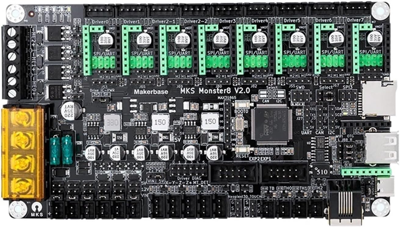
Figure 2: Top view of the Makerbase MKS Monster8 V2 control board, showing various driver slots (Driver0-Driver7), power input, and communication ports. This image highlights the arrangement of components on the board's top surface.
3.3 Power Supply Connection
Connect a compatible 12V/24V DC power supply to the designated power input terminals on the board. Ensure correct polarity to prevent damage.
3.4 Stepper Motor Driver Installation
The MKS Monster8 V2 supports up to 8 stepper motor drivers (e.g., TMC2209). Carefully insert each driver into its corresponding slot (Driver0 to Driver7), ensuring correct orientation. Refer to the driver's specific documentation for jumper settings if required.

Figure 3: Angled view of the Makerbase MKS Monster8 V2 control board, emphasizing the eight stepper motor driver slots and various peripheral connectors. This perspective helps visualize the board's depth and connection points.
3.5 Endstop and Sensor Connections
Connect your endstops (X, Y, Z) and other sensors (e.g., thermistors, filament runout sensor) to their respective pins on the board. Consult the board's pinout diagram for precise locations.
3.6 Firmware Flashing
The MKS Monster8 V2 requires firmware for operation. Download the latest compatible firmware (e.g., Marlin, Klipper) from the official Makerbase GitHub repository or your preferred firmware source. Flash the firmware to the board using a compatible method (e.g., SD card, USB DFU mode). Follow the specific instructions provided with the firmware.
4. Operating Instructions
4.1 Initial Power On and Testing
After all connections are secure and firmware is flashed, power on the board. Observe the indicator LEDs for proper operation. Connect to your computer via USB or network (if applicable) and use a host software (e.g., Pronterface, OctoPrint) to send G-code commands and test motor movements, endstops, and thermistor readings.
4.2 Configuration and Calibration
Calibrate your 3D printer's steps per millimeter, PID tuning for hotend and heated bed, and Z-offset. These settings are typically configured within the firmware or through G-code commands.
4.3 Printing Operations
Once calibrated, load your G-code file onto an SD card (if supported) or send it directly from your host software. Monitor the printing process and make adjustments as needed.
5. Maintenance
Regular maintenance ensures the longevity and optimal performance of your MKS Monster8 V2 board.
- Dust Removal: Periodically clean the board with compressed air or a soft brush to remove dust and debris, which can affect cooling and performance.
- Connection Check: Ensure all wire connections remain secure and free from corrosion.
- Firmware Updates: Keep the firmware updated to benefit from new features, bug fixes, and performance improvements.
- Environmental Conditions: Operate the board in a clean, dry environment with stable temperature to prevent damage from moisture or extreme heat/cold.
6. Troubleshooting
| Problem | Possible Cause | Solution |
|---|---|---|
| Board does not power on. | Incorrect power supply voltage or polarity; loose power connection; faulty power supply. | Verify power supply voltage (12V/24V) and polarity. Check power cable connections. Test power supply with a multimeter. |
| Stepper motors not moving. | Incorrect driver installation; wrong current setting; faulty motor or driver; firmware configuration error. | Ensure drivers are correctly inserted and oriented. Adjust driver current. Test motors and drivers individually. Check firmware motor definitions. |
| Temperature readings are incorrect. | Loose thermistor connection; incorrect thermistor type configured in firmware; faulty thermistor. | Check thermistor wiring. Verify thermistor type in firmware (e.g., TEMP_SENSOR_0). Replace thermistor if necessary. |
| USB connection issues. | Faulty USB cable; missing drivers; incorrect COM port selection. | Try a different USB cable. Install necessary USB drivers for the board. Select the correct COM port in your host software. |
| Board resets unexpectedly. | Insufficient power supply; short circuit; overheating. | Ensure power supply can provide sufficient current. Check for any short circuits on the board or connected components. Ensure adequate cooling. |
| Print quality issues (e.g., layer shifts). | Motor current too low; mechanical issues with printer; incorrect acceleration/jerk settings. | Increase motor current slightly. Inspect printer mechanics (belts, pulleys). Adjust firmware acceleration/jerk settings. |
7. Specifications
| Feature | Detail |
|---|---|
| Model Number | MKS-Monster8 V2 |
| Item Type | Motherboard / Control Board |
| Compatibility | Voron, Spider, Octopus systems (Suit 3 variant) |
| Processor | 32-bit |
| Stepper Driver Support | 8 driver slots (e.g., TMC2209) |
| Power Input | 12V/24V DC |
| Dimensions (Package) | 0.39 x 0.39 x 0.39 inches |
| Item Weight | 1.76 ounces (50 Grams) |
| Manufacturer | HJH62js |
| Assembly Required | No (for the board itself, but integration into a printer requires assembly) |
| Number of Pieces | 1 (for the board) |
| Color | Black (Suit 3 variant) |
| ASIN | B0F5Q483G2 |
| Brand | HRYKCBNJ |
| Model Number (Manufacturer) | HJH62js |
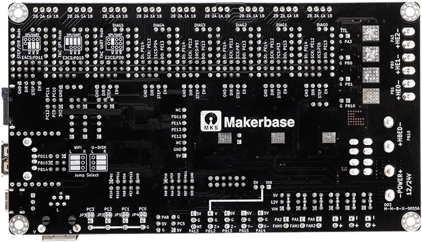
Figure 4: Bottom view of the Makerbase MKS Monster8 V2 control board, showing various solder points, component placements, and the Makerbase logo. This view provides insight into the board's internal design and manufacturing quality.
8. Warranty and Support
For warranty information and technical support, please refer to the official HRYKCBNJ or Makerbase website, or contact your point of purchase. Keep your purchase receipt as proof of purchase.
For common issues and community support, consider visiting online forums and communities dedicated to 3D printing and Makerbase products.