
Gain Express SLM-441_R1
Sound Level Tester Decibel Meter Datalogger User Manual
Model: SLM-441_R1 | Brand: Gain Express
1. Introduction
This manual provides detailed instructions for the safe and effective operation of your Gain Express Sound Level Tester Decibel Meter Datalogger, Model SLM-441_R1. This device is designed for accurate measurement and logging of sound levels, featuring A/C frequency weighting, Fast/Slow response times, and extensive data storage capabilities. It is an essential tool for industrial, environmental, and occupational noise assessments.
2. Safety Information
- Always handle the device with care to prevent damage.
- Do not expose the device to extreme temperatures, humidity, or direct sunlight.
- Avoid dropping the device or subjecting it to strong impacts.
- Do not attempt to disassemble or modify the device, as this will void the warranty and may cause damage or injury.
- Keep the device away from water and other liquids.
- Use only the provided USB cable for charging and data transfer.
3. Package Contents
Verify that all items listed below are present in your package:
- 1 x Sound Level Meter (Model SLM-441_R1)
- 1 x Windproof Sponge Ball
- 1 x USB Cable (Type-C)
- 1 x English Instruction Manual

4. Product Overview
Familiarize yourself with the components and features of your sound level meter.

Key Features:
- Real-time Measurement: Provides instant sound level readings.
- A/C Frequency Weighting: Allows selection between A-weighting (for environmental noise) and C-weighting (for sound pressure analysis of engines).
- Data Hold Function: Freezes the current reading on the display.
- 43,000 Data Record Function: Stores a large volume of measurement data.
- Fast/Slow Time Weighting: Selectable response times for different measurement scenarios.
- Three-color Light Alarm: Visual alerts for configurable high/low alarm thresholds.
- USB Power & PC Connect: Enables charging and data transfer to a computer.
- Auto Power Off Function: Conserves battery life.

5. Setup and Initial Use
5.1 Charging the Device
Before first use, fully charge the device. Connect the provided USB Type-C cable to the meter's Type-C interface and the other end to a USB power adapter (not included) or a computer's USB port. The charging time is approximately 1.5 hours, providing up to 8 hours of operation.
5.2 Attaching the Windproof Sponge Ball
Gently place the windproof sponge ball over the microphone at the top of the device. This helps to reduce wind noise interference during outdoor measurements.
5.3 Powering On/Off
Press and hold the POWER/ENTER button to turn the device on or off.
6. Operation
6.1 Basic Measurement
Once powered on, the device will immediately begin displaying real-time sound level readings in decibels (dB) on the LCD screen. The screen also shows maximum (max) and minimum (min) values, along with a real-time line graph of the sound fluctuations.

6.2 Frequency Weighting (A/C)
The device supports two frequency weighting modes:
- A-Weighting (A): Suitable for environmental noise detection, mimicking the human ear's response to sound.
- C-Weighting (C): Suitable for sound pressure analysis of engines and other mechanical noise, providing a flatter response across the frequency spectrum.
Press the A/C button to toggle between A and C weighting modes.

6.3 Time Weighting (FAST/SLOW)
The device offers two time weighting settings:
- FAST: Samples 8 times per second, ideal for environmental measurements with large variations in noise levels.
- SLOW: Samples 1 time per second, suitable for general environmental measurements where noise levels are relatively stable.
Press the F/S button to switch between FAST and SLOW response times.
6.4 Alarm Settings and Visualization
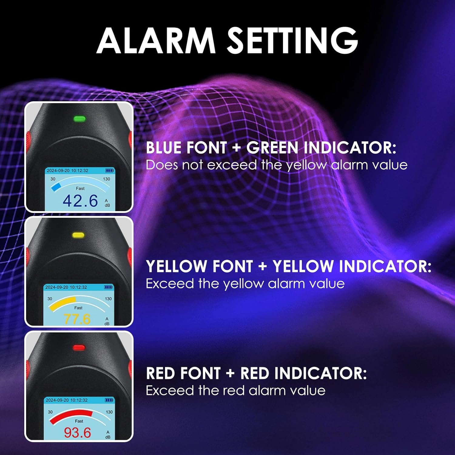
The device features a three-color LED alarm (green/yellow/red) and an on-device line chart to visualize real-time noise fluctuations. You can configure high/low alarm thresholds to receive immediate alerts when limits are exceeded.
- Blue Font + Green Indicator: Noise level does not exceed the yellow alarm value.
- Yellow Font + Yellow Indicator: Noise level exceeds the yellow alarm value.
- Red Font + Red Indicator: Noise level exceeds the red alarm value.
Refer to the device's on-screen menu (accessed via the SET button) to adjust alarm thresholds.
6.5 Data Management and PC Connectivity
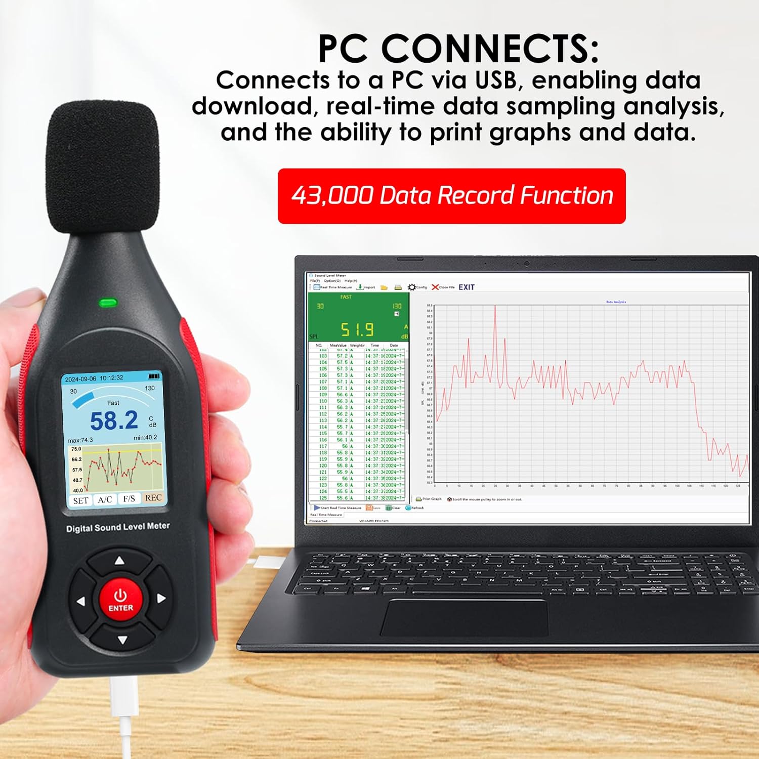
The meter can store up to 43,000 timestamped readings. You can review, delete, or download this data for in-depth analysis.
6.5.1 On-Device Data Review
Navigate through the device's menu using the directional buttons to access saved data records. The LCD screen interface allows you to view recorded values and their corresponding timestamps, along with a graph of the recorded data.

6.5.2 PC Connection and Software
Connect the meter to a Windows 7/10/11 PC via the USB-C port. This enables data download, real-time data sampling analysis, and the ability to print graphs and reports. The device typically functions as a mass storage device or requires specific software for full functionality. Refer to the included manual for software installation instructions.
6.6 DC Output
The device features a DC output port (3.5mm jack) that provides the noise value in voltage mode according to proportion. The DC voltage range is 300mV to 1300mV, with a DC voltage error of ±5mV and DC impedance of 120R. The relationship between DC output voltage (Vout) and noise value (dB) is Vout = dB x 10 (unit: mV).
This feature is useful for integration with other data logging systems or for real-time monitoring applications.
Video 6.1: Demonstration of the Sound Level Meter's features and operation, including its display and connectivity options.
This video provides a visual guide to the sound level meter's functionality, demonstrating how to navigate menus, view real-time data, and utilize its various features. It showcases the device's compact size and ease of use.
7. Maintenance
- Cleaning: Use a soft, dry cloth to clean the device. Do not use abrasive cleaners or solvents.
- Storage: When not in use for extended periods, store the device in a cool, dry place, away from direct sunlight and extreme temperatures.
- Battery Care: To prolong battery life, avoid fully discharging the battery frequently. Recharge the device regularly, even if not in active use.
- Microphone Protection: Always use the windproof sponge ball to protect the microphone from dust and debris.
8. Troubleshooting
| Problem | Possible Cause | Solution |
|---|---|---|
| Device does not power on. | Low battery. | Charge the device using the provided USB cable. |
| Inaccurate readings. | Microphone obstructed or damaged; incorrect weighting setting. | Ensure microphone is clear; check A/C and Fast/Slow settings. Consider calibration if issues persist. |
| Cannot connect to PC. | Incorrect USB cable; driver issues; software not installed. | Use the provided USB cable; install necessary drivers/software from the manufacturer's website or included media. |
| Display is dim or blank. | Low battery; device malfunction. | Charge the device. If problem persists, contact customer support. |
9. Specifications
| Parameter | Value |
|---|---|
| Calibration Sound Source | 94dB@1KHz |
| Measurement Range | 30~130dB (A), 35~130dB (C) |
| Accuracy | ±1.5dB (Reference sound pressure standard, 94dB@1KHz) |
| Resolution | 0.1dB |
| Frequency Weighting | A/C |
| Frequency Response | 31.5~8500Hz |
| Time-weighting | FAST/SLOW |
| Sampling Rate | FAST - 8 times/second; SLOW - 1 times/second |
| Rated Current | 70mA |
| Standby Current | 5uA |
| Power Supply | 3.7V lithium battery / 1000mAh |
| Charging Time | 1.5h |
| Duration of Service | 8h |
| Data Storage | 43,000 records |
| Microphone | 1/2-inch polarization capacitance microphone |
| Operating Environment | 0~50°C; 10~80% RH |
| Dimension (excluding sponge ball) | 160 x 56 x 31mm |
| Weight (excluding sponge ball) | approx. 114gms |
| DC Output Voltage Range | 300mV~1300mV |
| DC Output Voltage Error | ±5mV |
| DC Impedance | 120R |
| DC and Noise Relationship | Vout=dB x 10 (unit: mV) |
10. Warranty and Support
For warranty information and technical support, please refer to the contact details provided with your purchase or visit the official Gain Express website. Keep your purchase receipt as proof of purchase for any warranty claims.
The manufacturer, Gain Express Holdings Ltd., is committed to providing reliable products and customer service.
Ask a question about this manual
Ask about setup, troubleshooting, compatibility, parts, safety, or missing instructions. Manuals+ will review the question and use this page’s manual context to help answer it.