1. Introduction
This manual provides detailed instructions for the installation, operation, and maintenance of your VEVOR PC Gaming Case, Model 230-14. Please read this manual thoroughly before beginning assembly to ensure proper setup and to maximize the performance and longevity of your computer components.
The VEVOR PC Gaming Case is designed to accommodate ATX, M-ATX, and ITX motherboards, offering extensive storage options and efficient cooling solutions for a high-performance computing experience.
2. Safety Information
- Always disconnect the power supply from the wall outlet before installing or removing any components.
- Handle all components with care to prevent damage from static electricity. Consider using an anti-static wrist strap.
- Be aware of sharp edges inside the case during installation.
- Ensure all cables are properly routed and secured to avoid interference with fans or other moving parts.
- Do not obstruct the ventilation openings of the case.
3. Package Contents
Verify that all items are present in the package:
- VEVOR PC Gaming Case (Model 230-14)
- 4 x 120mm Cooling Fans (pre-installed)
- Accessory Box (containing screws, standoffs, cable ties, etc.)
- User Manual (this document)
4. Setup and Installation
4.1 Case Overview
Familiarize yourself with the internal layout and external features of the VEVOR PC Gaming Case.
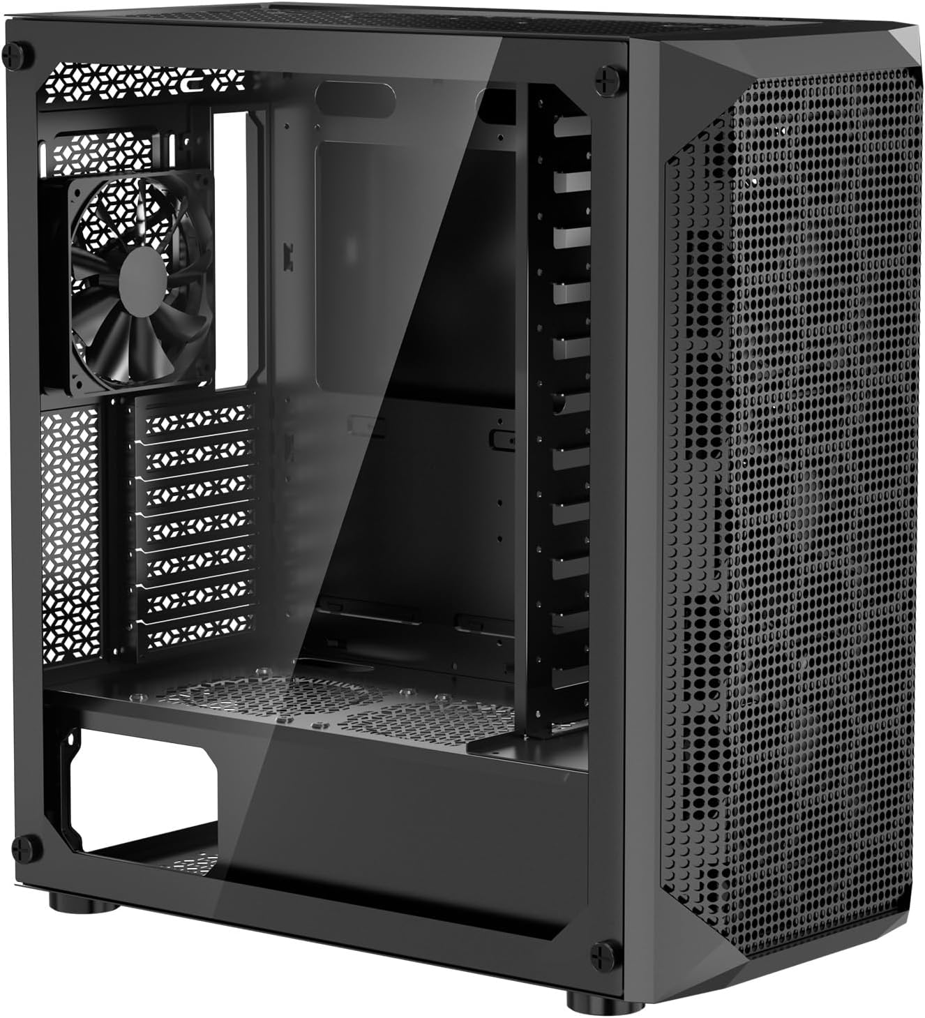
Image 4.1: Front-side view of the VEVOR PC Gaming Case, Model 230-14, showcasing its tempered glass side panel and mesh front panel for airflow.
4.2 Motherboard Installation
The case supports ATX, M-ATX, and ITX motherboards. Identify the correct standoff positions for your motherboard size.
- Remove the tempered glass side panel by unscrewing the thumb screws.
- Install the I/O shield provided with your motherboard into the rear opening of the case.
- Align your motherboard with the pre-installed standoffs. If necessary, install additional standoffs from the accessory box according to your motherboard's form factor.
- Carefully place the motherboard onto the standoffs and secure it with the provided screws.
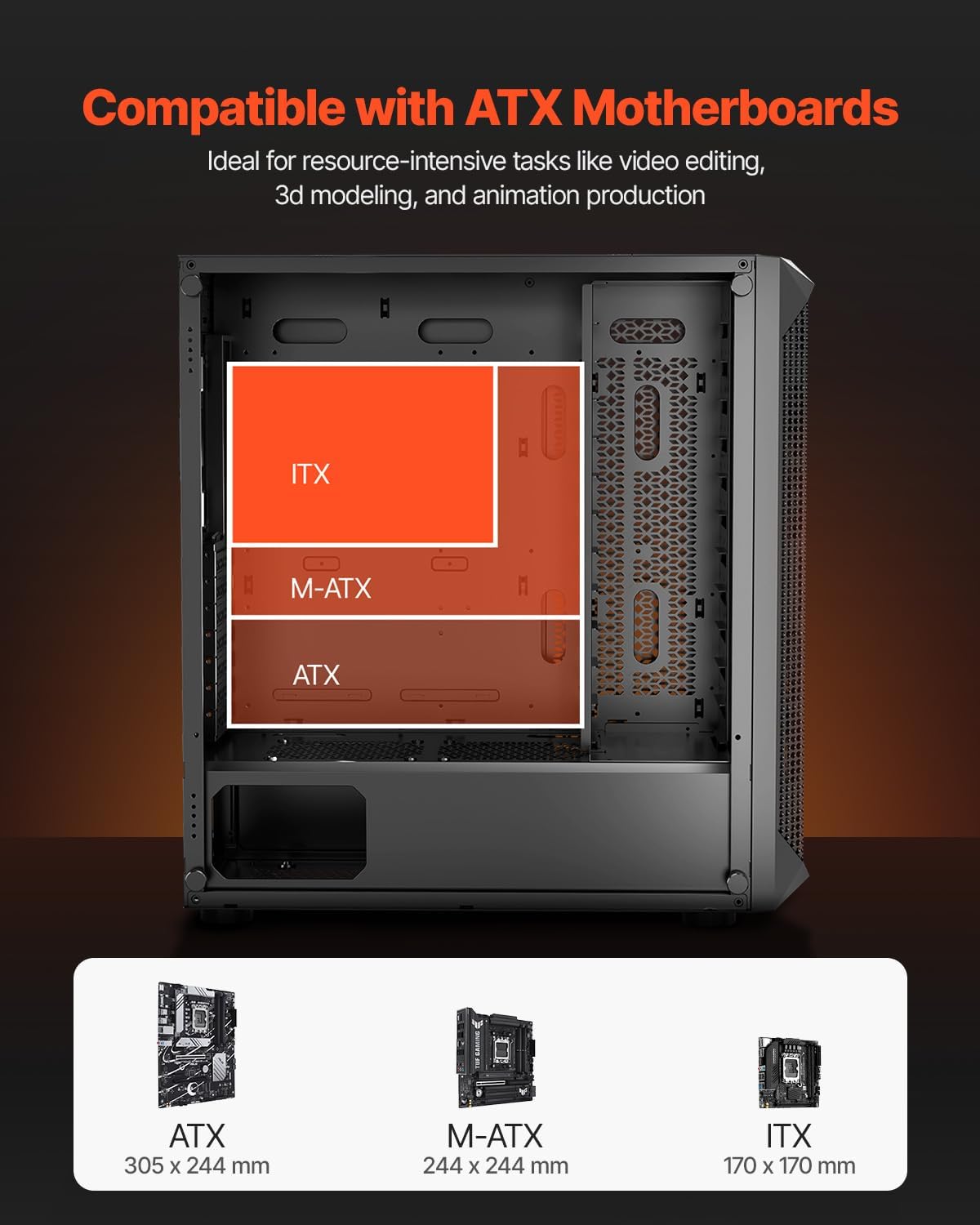
Image 4.2: Diagram illustrating motherboard compatibility for ATX, M-ATX, and ITX form factors within the case, showing their respective mounting areas.
4.3 Storage Device Installation
The case offers extensive storage capacity, supporting up to 16 hard disks (2 x SSD + 14 x HDD or 3 x SSD + 13 x HDD).
- Locate the dedicated mounting points for 2.5-inch SSDs and 3.5-inch HDDs.
- For 2.5-inch SSDs, secure them to the designated trays or mounting brackets using the appropriate screws.
- For 3.5-inch HDDs, slide them into the drive cages and secure them with screws. Note that some drive cages may require removal for initial installation of multiple drives.

Image 4.3: Internal view of the case highlighting the various mounting locations for SSDs and HDDs, indicating support for up to 16 drives.
4.4 GPU Installation
The case supports GPUs up to 270 mm in length.
- Remove the necessary expansion slot covers from the rear of the case.
- Insert your graphics card into the appropriate PCIe slot on your motherboard.
- Secure the graphics card to the case with screws.

Image 4.4: Diagram showing the maximum GPU length supported (270 mm) within the case, with examples of compatible graphics cards.
4.5 Fan and Cooling System Installation
The case comes with 4 x 120mm fans pre-installed and supports up to 7 x 120mm fans or 5 x 140mm fans + 1 x 120mm fan for optimal airflow.
- Ensure all pre-installed fans are correctly connected to your motherboard or power supply.
- If installing additional fans or a liquid cooling radiator, refer to the case's fan mounting points (front, top, rear).
- Secure fans with appropriate screws. Radiators should be mounted according to their specific instructions.

Image 4.5: Diagram illustrating the case's cooling capabilities, showing locations for 120mm and 140mm fans and radiator support for 240mm.
4.6 Cable Management
The case features a design to facilitate proper cable management, keeping the interior tidy and improving airflow.
- Route power supply cables and data cables through the cutouts and behind the motherboard tray.
- Utilize the included cable ties to bundle and secure cables, preventing them from obstructing airflow or components.
- Ensure sufficient clearance for the side panel to close without pinching cables.

Image 4.6: Rear interior view of the case demonstrating the cable management channels and tie-down points behind the motherboard tray.
5. Operating Instructions
5.1 Front I/O Panel Functions
The front I/O panel provides convenient access to essential ports and controls.

Image 5.1: Close-up view of the front I/O panel, detailing the location and function of each port and button.
- Power Button: Press to turn the computer on or off.
- Reset Button: Press to restart the computer.
- USB 3.0 Type-A Port (x1): For high-speed data transfer with compatible devices.
- USB 2.0 Type-A Ports (x2): For connecting peripherals such as keyboards, mice, or USB drives.
- Microphone Jack: For connecting a microphone.
- Audio Jack: For connecting headphones or speakers.
- LED/Lighting Control Button: If applicable, controls the lighting effects of compatible RGB components.
6. Maintenance
6.1 Dust Filter Cleaning
Regular cleaning of the dust filters is crucial for maintaining optimal airflow and preventing dust buildup inside your PC.
- The case is equipped with fine mesh dust filters on the top, bottom, side, and front panels.
- The magnetic dust filters on the top and side panels can be easily detached for cleaning.
- Gently remove the filters and clean them using compressed air or by rinsing with water. Ensure they are completely dry before reattaching.
- For non-magnetic filters, carefully remove them and clean as described above.

Image 6.1: Exploded view of the case showing the locations of the removable dust filters on the top, side, and bottom panels.
7. Troubleshooting
- Issue: Fans are not spinning or not lighting up.
Solution: Check fan power connections. Ensure they are securely plugged into the motherboard fan headers or directly to the power supply. Some fans may use Molex connectors, which need to be connected to a compatible power supply cable. Verify that any lighting control cables are correctly connected to the motherboard or a dedicated controller. - Issue: Motherboard does not fit or align with standoffs.
Solution: Confirm your motherboard's form factor (ATX, M-ATX, ITX) and ensure the standoffs are installed in the correct positions for your specific board. Refer to your motherboard manual for exact mounting hole locations. - Issue: Side panel does not close properly after installation.
Solution: This often indicates poor cable management. Ensure all cables are routed behind the motherboard tray and secured with cable ties, avoiding any bulging that would prevent the panel from closing flush. - Issue: Difficulty installing multiple 3.5-inch HDDs.
Solution: The drive cage design may require careful planning. It is recommended to install all planned 3.5-inch HDDs at once to avoid repeatedly removing and re-installing the cage. Ensure power and data cables are connected before fully securing the cage, especially if space is limited.
8. Specifications
Detailed technical specifications for the VEVOR PC Gaming Case Model 230-14.

Image 8.1: Diagram showing key dimensions and a summary of technical specifications for the VEVOR PC Gaming Case.
| Feature | Specification |
|---|---|
| Model Number | 230-14 |
| Case Type | Mid Tower |
| Motherboard Compatibility | ATX, M-ATX, ITX |
| Material | SPCC Steel, Tempered Glass |
| Pre-installed Fans | 4 x 120mm Fans |
| Max Fan Support | 7 x 120mm Fans or 5 x 140mm Fans + 1 x 120mm Fan |
| GPU Max Length | 270 mm |
| Expansion Slots | 7 |
| Storage Support | Up to 16 drives (2 x SSD + 14 x HDD or 3 x SSD + 13 x HDD) |
| Front I/O Ports | 1 x USB 3.0, 2 x USB 2.0, Microphone Jack, Audio Jack, Power Button, Reset Button, LED Control Button |
| Product Dimensions (L x W x H) | 465 x 230 x 495 mm (18.31 x 9.06 x 19.49 inches) |
| Item Weight | 7.66 kg (16.9 lbs) |
9. Warranty and Support
For warranty information, technical support, or service inquiries, please refer to the official VEVOR website or contact their customer service department. Keep your purchase receipt as proof of purchase for any warranty claims.
For further assistance, please visit: www.vevor.com