1. Introduction
This manual provides essential instructions for the proper installation, operation, and maintenance of your LCWLYOBM 20kW Single-phase Excitation Automatic Voltage Regulator (AVR) Kit, models 9-1B1L and 9-1B2L. The AVR is designed to automatically maintain a constant output voltage from a generator, ensuring stable power delivery. Please read this manual thoroughly before attempting any installation or operation to ensure safe and efficient use of the product.
2. Safety Information
Working with electrical components, especially high-power devices like voltage regulators, carries inherent risks. Adhere to the following safety guidelines:
- Professional Installation: Installation should only be performed by qualified personnel with experience in electrical systems and generator maintenance.
- Power Disconnection: Always ensure the generator and any associated power sources are completely disconnected and locked out before beginning installation, maintenance, or troubleshooting.
- Electrical Shock Hazard: High voltages are present within the AVR and generator system. Contact with live circuits can cause severe injury or death.
- Proper Grounding: Ensure all equipment is correctly grounded according to local electrical codes and manufacturer specifications.
- Environmental Conditions: Do not expose the AVR to moisture, extreme temperatures, or corrosive environments.
- Component Integrity: Do not operate the AVR if it appears damaged or if any components are loose or missing.
3. Product Overview
The LCWLYOBM Automatic Voltage Regulator is a compact electronic device designed to regulate the output voltage of a single-phase generator. It features robust construction with a heat sink for thermal management and clearly labeled terminals for connection.

Figure 3.1: The LCWLYOBM 20kW Single-phase Excitation Automatic Voltage Regulator (AVR) module, shown alongside its brown cardboard packaging box. The AVR features a black casing, a prominent heat sink, and various electronic components.

Figure 3.2: A direct top-down view of the AVR module, highlighting the heat sink with a yellow warning symbol, the large capacitor, and the terminal block connections on the left side.
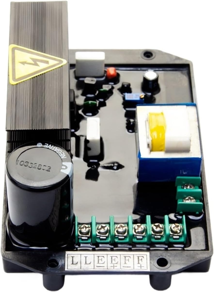
Figure 3.3: A close-up view of the green terminal blocks on the AVR, showing the screw terminals for electrical connections. Labels such as 'L', 'L', 'E', 'E', 'F', 'F' are visible, indicating connection points for the generator.
4. Specifications
The following table details the key specifications for the LCWLYOBM 20kW Single-phase Excitation Automatic Voltage Regulator:
| Feature | Specification |
|---|---|
| Brand | LCWLYOBM |
| Model | 9-1B1L / 9-1B2L (20kW) |
| Item Weight | 1.76 ounces |
| Package Dimensions | 0.39 x 0.39 x 0.39 inches |
| Manufacturer | LCWLYOBM |
| ASIN | B0F5MY42B1 |
5. Setup
Proper setup is crucial for the correct functioning and longevity of the AVR. Always ensure safety precautions are followed before proceeding.
- Mounting: Securely mount the AVR in a location that is free from excessive vibration, moisture, and direct heat. Ensure adequate ventilation around the heat sink.
- Wiring Identification: Carefully identify the generator's excitation winding terminals (typically F+ and F- or similar), sensing voltage terminals (typically L and N or similar), and auxiliary power input terminals (if applicable). Refer to your generator's specific wiring diagram.
- Connection: Connect the AVR terminals to the corresponding generator terminals. Ensure all connections are tight and secure to prevent loose contacts, which can cause arcing or damage.
- Initial Voltage Adjustment: Some AVRs may have a voltage adjustment potentiometer. Before starting the generator, ensure this is set to a nominal position, usually mid-range. Fine-tuning will occur during operation.
- Double-Check: Before restoring power, meticulously double-check all wiring connections against the generator's wiring diagram and the AVR's terminal labels.
Note: Specific wiring diagrams are dependent on the generator model. Consult your generator's manual for detailed connection instructions.
6. Operating Instructions
Once the AVR is correctly installed and all safety checks are complete, you can proceed with operating the generator.
- Start Generator: Start the generator according to its manufacturer's instructions.
- Monitor Output Voltage: Observe the generator's output voltage using a voltmeter. The AVR should automatically regulate the voltage to the set point.
- Voltage Adjustment (if necessary): If the output voltage is not at the desired level, carefully adjust the voltage potentiometer on the AVR (if present) until the correct voltage is achieved. Make small adjustments and allow the system to stabilize.
- Load Application: Once the voltage is stable, you can gradually apply the load to the generator. The AVR will continuously monitor and adjust the excitation to maintain a stable output voltage under varying load conditions.
- Shutdown: To shut down the generator, follow the generator manufacturer's instructions. The AVR will cease operation as the generator powers down.
7. Maintenance
The LCWLYOBM AVR is designed for reliable operation with minimal maintenance. However, periodic checks can help ensure its longevity and performance.
- Visual Inspection: Regularly inspect the AVR for any signs of physical damage, loose connections, discoloration, or overheating.
- Cleanliness: Keep the AVR free from dust, dirt, and debris. Use a soft, dry brush or compressed air to clean the unit, especially the heat sink, to ensure proper cooling.
- Connection Integrity: Periodically check all electrical connections to ensure they remain tight and free from corrosion.
- Environmental Check: Ensure the operating environment remains within specified conditions (temperature, humidity).
Always disconnect power before performing any maintenance.
8. Troubleshooting
If you encounter issues with your AVR, consider the following common troubleshooting steps:
- No Output Voltage:
- Check all wiring connections for looseness or incorrect placement.
- Verify the generator's excitation winding is intact.
- Ensure the AVR is receiving proper sensing voltage.
- Unstable Output Voltage:
- Check for loose connections.
- Ensure the generator engine speed is stable.
- Verify the AVR's voltage adjustment potentiometer is not overly sensitive or faulty.
- Overvoltage/Undervoltage:
- Adjust the voltage potentiometer on the AVR.
- Ensure the AVR is correctly matched to the generator's specifications.
- Overheating:
- Check for adequate ventilation around the AVR.
- Ensure the AVR is not overloaded beyond its rated capacity.
- Clean any dust or debris from the heat sink.
If problems persist after performing these checks, contact qualified service personnel or the manufacturer for assistance.
9. Warranty Information
Specific warranty terms and conditions for the LCWLYOBM 20kW Single-phase Excitation Automatic Voltage Regulator (AVR) Kit are provided by the manufacturer or seller at the time of purchase. Please refer to your purchase documentation or contact the seller directly for detailed warranty coverage, duration, and claim procedures.
10. Support
For technical assistance, troubleshooting beyond the scope of this manual, or inquiries regarding parts and service, please contact LCWLYOBM customer support or your authorized dealer. When contacting support, please have your product model number (9-1B1L or 9-1B2L) and purchase information readily available.