1. Introduction
This manual provides detailed instructions for the installation, operation, and maintenance of the WVCLTVJA (LM8-RR4D) Load Cell Indicator and Weighing Controller. This device is designed to accurately measure and display weight from 1 to 4 load cell inputs and provides 2 relay outputs for control applications. Please read this manual thoroughly before use to ensure proper functionality and safety.
2. Safety Information
- Electrical Safety: Ensure the power supply matches the device's requirements (AC 220V/110V). Disconnect power before making any wiring connections or performing maintenance.
- Qualified Personnel: Installation and wiring should only be performed by qualified personnel to prevent electric shock or damage to the device.
- Environment: Do not expose the device to excessive moisture, dust, corrosive gases, or extreme temperatures. Operate within specified environmental conditions.
- Grounding: Ensure proper grounding to prevent electrical hazards.
- Load Cell Compatibility: Use load cells compatible with the indicator's input specifications.
3. Product Overview
3.1 Front Panel
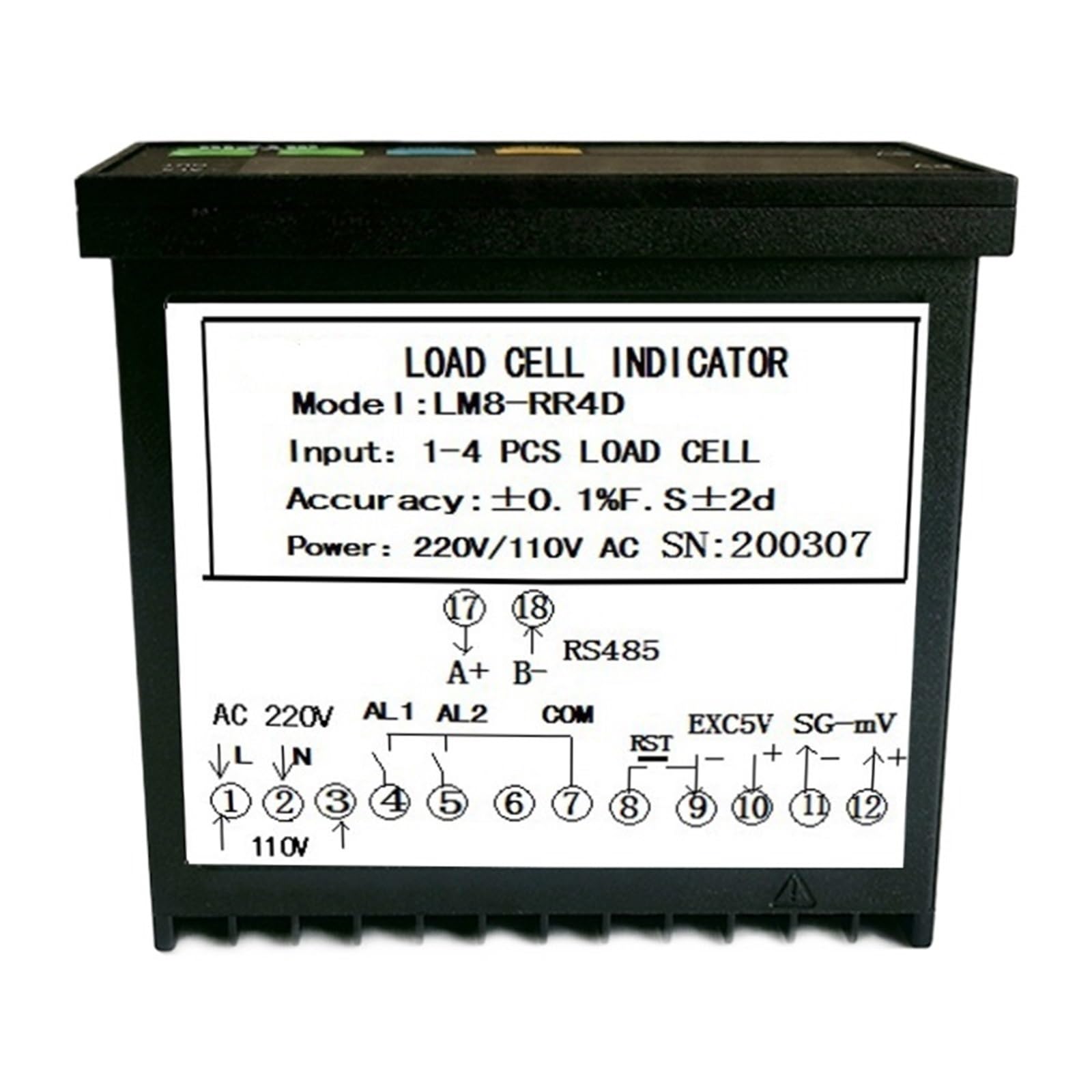
Figure 1: Front Panel of the LM8-RR4D Load Cell Indicator. It features a large red LED display for Process Value (PV) and a smaller green LED display for Set Value (SV). Indicators for 'LM' (Limit), 'g', 'AL1', 'AL2', 'AL3', 'T' (Tare), and 'Kg' are also present. Control buttons include 'SET', 'M' (Mode/Shift), 'Up', and 'Down'.
- PV Display: Large red LED display showing the current measured weight (Process Value).
- SV Display: Smaller green LED display showing the set point or parameter value (Set Value).
- Indicators: 'g' (grams), 'Kg' (kilograms), 'T' (Tare), 'AL1', 'AL2', 'AL3' (Alarm indicators), 'LM' (Limit).
- Buttons:
- SET: Enters parameter setting mode or confirms settings.
- M (Mode/Shift): Used to cycle through modes or shift digits during setting.
- Up (▲): Increases values or navigates menus.
- Down (▼): Decreases values or navigates menus.
3.2 Rear Panel & Wiring Terminals

Figure 2: Rear Panel of the LM8-RR4D Load Cell Indicator, displaying numbered screw terminals for power, load cell input, and relay outputs. The wiring diagram is also visible on the label.
The rear panel provides all necessary connections for power, load cells, and relay outputs. Refer to the wiring diagram printed on the device label for specific terminal assignments.
4. Setup and Installation
4.1 Mounting
The LM8-RR4D is designed for panel mounting. Ensure adequate space for ventilation and wiring connections. Secure the device firmly in the panel cutout.
4.2 Wiring Connections
Before making any connections, ensure the power supply is disconnected. Refer to the wiring diagram on the device label and Figure 2 for terminal identification.
- Power Supply (AC 220V/110V): Connect the appropriate AC power supply to the designated terminals (e.g., 110V/220V, N, L). Ensure the voltage matches your local supply and the device's setting.
- Load Cell Input:
- Connect the load cell excitation voltage wires (EXC+, EXC-) to the corresponding terminals.
- Connect the load cell signal wires (SIG+, SIG-) to the corresponding terminals.
- The device supports 1 to 4 load cells. For multiple load cells, ensure they are wired in parallel correctly.
- Relay Outputs (AL1, AL2):
- Connect your external control devices (e.g., alarms, solenoids) to the AL1 and AL2 relay output terminals.
- Each relay typically has Common (COM), Normally Open (NO), and Normally Closed (NC) contacts. Wire according to your application's requirements.
- Communication (Optional, if available): If your model includes RS485 communication, connect the A and B lines to the respective terminals for data transmission.
After all connections are made, double-check wiring for correctness and security before applying power.
5. Operating Instructions
5.1 Power On
Once wired, apply power. The LED display will illuminate, showing the current weight (PV) and potentially a set value (SV).
5.2 Basic Operation
- Zeroing/Tare: Pressing the 'M' button briefly may perform a tare function, setting the current weight to zero. Consult the full manual for specific tare procedures.
- Unit Selection: The 'g' and 'Kg' indicators suggest unit selection. This is typically done through parameter settings.
5.3 Parameter Setting and Calibration
The LM8-RR4D requires calibration to ensure accurate weight readings. This involves setting zero and span points using known weights.
- Enter Setting Mode: Press and hold the 'SET' button for a few seconds to enter the parameter setting mode. The SV display will show a parameter code.
- Navigate Parameters: Use the 'Up' (▲) and 'Down' (▼) buttons to scroll through different parameter codes.
- Adjust Parameter Value: When the desired parameter code is displayed, press 'SET' again to view its current value. Use 'Up' (▲) and 'Down' (▼) to adjust the value. The 'M' button may be used to shift digits.
- Save and Exit: Press 'SET' to confirm the value. To exit the setting mode, press and hold 'SET' again, or the device may automatically exit after a period of inactivity.
Specific parameter codes and their functions (e.g., zero calibration, span calibration, decimal point, filter settings, alarm set points for AL1/AL2) are detailed in the comprehensive product manual.
6. Maintenance
- Cleaning: Clean the device exterior with a soft, dry cloth. Do not use abrasive cleaners or solvents. Ensure no liquids enter the device.
- Inspection: Periodically check wiring connections for looseness or damage. Ensure the mounting is secure.
- Recalibration: If accuracy drifts or after significant environmental changes, recalibrate the device using known weights.
- Storage: If storing the device, do so in a dry, dust-free environment within the specified temperature range.
7. Troubleshooting
| Problem | Possible Cause | Solution |
|---|---|---|
| No display / Device not powering on | No power supply; Incorrect wiring; Blown fuse. | Check power connections; Verify voltage; Inspect internal fuse (if accessible and safe). |
| Inaccurate weight readings | Incorrect calibration; Damaged load cell; Loose load cell wiring; Environmental interference. | Perform recalibration; Check load cell integrity; Secure all load cell wiring; Minimize vibrations or drafts. |
| Display shows "OVER" or "UNDER" | Weight exceeds/falls below measurement range; Load cell capacity exceeded; Incorrect calibration. | Ensure weight is within range; Verify load cell capacity; Recalibrate. |
| Relay outputs not activating | Incorrect alarm set points; Relay wiring error; Relay malfunction. | Check AL1/AL2 set points; Verify relay output wiring; Test relay functionality. |
| Unstable readings | Vibrations; Electrical noise; Faulty load cell; Loose connections. | Isolate from vibrations; Check grounding; Inspect load cell and wiring. |
If the problem persists after attempting these solutions, contact customer support.
8. Specifications
| Parameter | Value |
|---|---|
| Model | LM8-RR4D |
| Input Type | 1-4 Load Cell Signals |
| Output Type | 2 Relay Outputs (AL1, AL2) |
| Power Supply | AC 220V / 110V (selectable/auto-sensing, refer to device label) |
| Accuracy | LO. 2%F.S ± 2d |
| Display | LED (PV: Red, SV: Green) |
| Package Dimensions | 11.81 x 7.87 x 3.94 inches |
| Item Weight | 1.76 ounces |
| Manufacturer | WVCLTVJA |
9. Warranty and Support
For warranty information and technical support, please refer to the documentation provided with your purchase or contact your vendor. Keep your purchase receipt as proof of purchase.