1. Introduction
This manual provides essential information for the safe and effective operation, setup, and maintenance of your PANERGYRIC MIG/MMA-300 Dipulse PRO welding machine. This versatile 5-in-1 welder supports Gas MIG, Gasless Flux Core MIG, Pulse MIG, Stick/MMA, and Lift TIG welding processes. Please read this manual thoroughly before use to ensure proper functionality and safety.

Image 1.1: The PANERGYRIC MIG/MMA-300 Dipulse PRO welding machine, highlighting its multi-process capabilities in a typical workshop environment.
2. Safety Information
Welding operations involve inherent risks. Always prioritize safety to prevent injury or damage to equipment. Adhere to all local and national safety regulations.
General Safety Precautions:
- Wear appropriate personal protective equipment (PPE), including a welding helmet with proper shade, flame-resistant clothing, welding gloves, and safety shoes.
- Ensure adequate ventilation in the work area to disperse fumes and gases.
- Keep a fire extinguisher readily available.
- Never weld near flammable materials.
- Ensure the welding machine is properly grounded.
- Disconnect power before performing any maintenance or adjustments.

Image 2.1: Rear view of the welding machine, illustrating built-in safety features such as IGBT technology, efficient cooling, and dual voltage input.
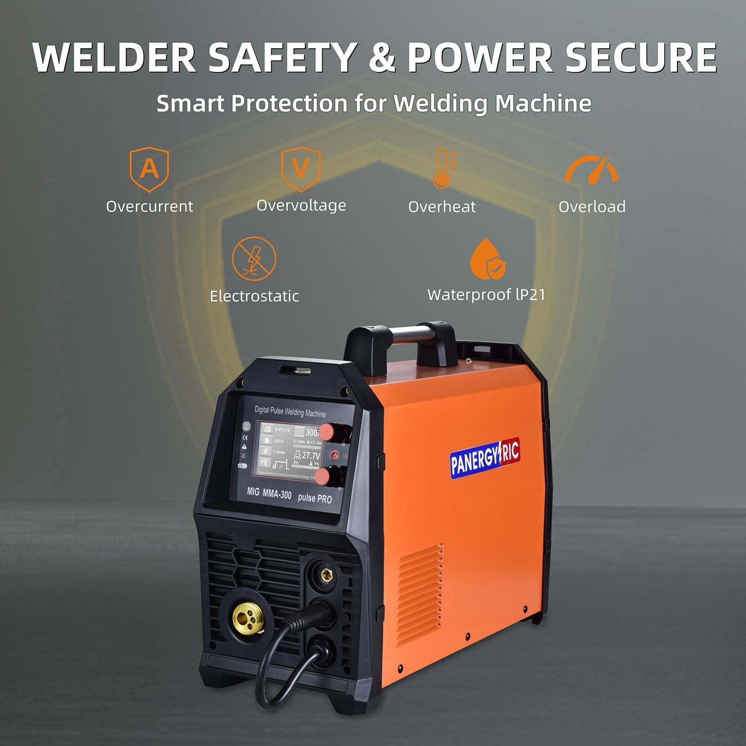
Image 2.2: Overview of the welder's smart protection systems, designed to safeguard against common electrical and environmental hazards.
3. Package Contents
Upon unpacking, verify that all items listed below are present and undamaged. If any components are missing or damaged, contact your vendor immediately.
- PANERGYRIC MIG/MMA-300 Dipulse PRO Welding Machine
- MIG Torch
- Electrode Holder
- Earth Clamp
- Gas Hose
- Conductive Nozzle (various sizes)
- 110V to 220V Wire Adapter
- Brush
- User Manual (this document)

Image 3.1: All components included with the PANERGYRIC MIG/MMA-300 Dipulse PRO welding machine.
4. Product Features
The PANERGYRIC MIG/MMA-300 Dipulse PRO is engineered with advanced features to enhance welding performance and user experience.
4.1. 5-in-1 Multifunctionality
This machine offers five distinct welding processes, providing versatility for various applications:
- Gas MIG: For welding with shielding gas.
- Gasless Flux Core MIG: For welding without external shielding gas, using flux-cored wire.
- Stick/MMA: Manual Metal Arc welding using coated electrodes.
- Lift TIG: Tungsten Inert Gas welding with lift arc ignition (TIG gun not included).
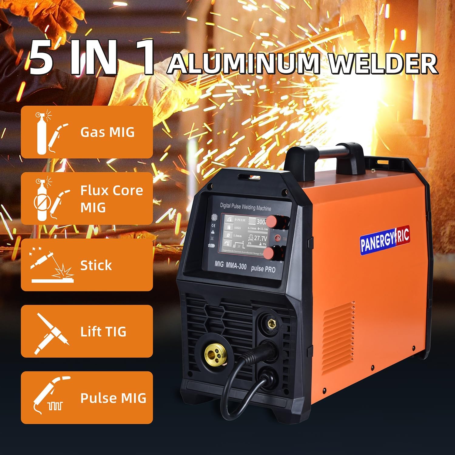
Image 4.1: Visual representation of the five welding modes supported by the machine.
4.2. Dipulse MIG for Aluminum
The Pulse MIG feature, specifically Dipulse, significantly improves aluminum welding. It provides a fast, high-quality, low-spatter weld with consistent aesthetics, making aluminum welding more accessible and efficient.
4.3. Digital LCD Display
The large LCD screen offers a clear and intuitive interface, displaying welding parameters such as current, voltage, wire feed speed, and selected mode. This allows for real-time adjustments without removing your welding helmet, enhancing efficiency and accuracy.

Image 4.2: Detailed view of the digital display, showing key welding parameters and control interface.
4.4. Synergic Control
Equipped with IGBT technology and integrated wire feed, the welder automatically matches recommended voltage and wire feed speed to the selected current. Users can also fine-tune voltage independently using the adjustment knob, catering to both beginners and experienced professionals.
4.5. Flexible Wire Compatibility
The machine supports various wire types and sizes, accommodating up to 11 lbs (5 kg) spools:
- Flux Core Wire: 0.03" (0.8mm) & 0.04" (1.0mm)
- Gas Solid Wire: 0.03" (0.8mm) & 0.04" (1.0mm)
- Aluminum Wire: 0.04" (1.0mm) & 0.05" (1.2mm)

Image 4.3: The internal wire feed system, designed for smooth and adjustable wire delivery.
5. Setup
Follow these steps for initial setup of your welding machine.
5.1. Power Connection
- Ensure the welder's power switch is in the OFF position.
- Connect the power cord to a suitable 110V or 220V power outlet. The machine features dual voltage capability and includes a 110V to 220V adapter.
- Verify the power source meets the machine's requirements to prevent damage.
5.2. Gas Connection (for Gas MIG/Pulse MIG/Lift TIG)
- Attach one end of the gas hose to the gas inlet on the rear of the welding machine.
- Connect the other end of the gas hose to your shielding gas cylinder regulator.
- Ensure all connections are secure and leak-free.
5.3. Wire Installation (for MIG/Pulse MIG/Flux Core MIG)
- Open the wire feed compartment.
- Place the wire spool onto the spool holder, ensuring it rotates freely.
- Thread the welding wire through the wire feed mechanism and into the MIG torch liner.
- Adjust the wire tension appropriately.
5.4. Torch and Clamp Connection
- Connect the MIG torch to the appropriate connector on the front panel.
- Connect the earth clamp cable to the designated terminal and securely attach the clamp to the workpiece or welding table.
- For Stick/MMA welding, connect the electrode holder to the positive terminal and the earth clamp to the negative terminal.
- For Lift TIG welding, connect the TIG torch (not included) to the appropriate terminal and the earth clamp to the workpiece.
6. Operating Modes
The PANERGYRIC MIG/MMA-300 Dipulse PRO offers multiple welding modes. Select the appropriate mode for your application using the control panel.

Image 6.1: Visual examples of the various welding processes achievable with this machine.
6.1. MIG Welding (Gas/Gasless Flux Core/Pulse)
- Select the desired MIG mode (Gas MIG, Flux Core MIG, or Pulse MIG) on the control panel.
- Adjust wire feed speed and voltage. Utilize the synergic control for automatic parameter matching or fine-tune manually.
- Ensure proper gas flow for Gas MIG and Pulse MIG.
- Begin welding, maintaining a consistent travel speed and arc length.
6.2. Stick/MMA Welding
- Select MMA mode.
- Insert the appropriate electrode into the electrode holder.
- Adjust the welding current (amperage) according to the electrode type and material thickness.
- Strike an arc and maintain a steady hand for consistent bead formation.
6.3. Lift TIG Welding
- Select Lift TIG mode.
- Ensure a TIG torch (not included) with a tungsten electrode is connected and proper shielding gas is flowing.
- Adjust the welding current.
- Initiate the arc by gently touching the tungsten to the workpiece and lifting it slightly.

Image 6.2: Examples of high-quality welds on aluminum and mild steel, showcasing the machine's precision.
7. Maintenance
Regular maintenance ensures the longevity and optimal performance of your welding machine.
- Daily: Clean the MIG torch nozzle and contact tip. Check for loose connections.
- Weekly: Inspect welding cables for damage. Clean the wire feed rollers and guide tubes.
- Monthly: Use compressed air to blow out dust and debris from inside the machine (ensure power is disconnected). Check cooling fan operation.
- Periodically: Inspect and replace worn parts such as contact tips, nozzles, and liners.
8. Troubleshooting
This section addresses common issues you might encounter. For problems not listed here, contact technical support.
| Problem | Possible Cause | Solution |
|---|---|---|
| No power | Power switch off, circuit breaker tripped, loose power cable | Turn on switch, reset breaker, check connections |
| No arc | Poor earth connection, wrong mode, faulty torch/electrode holder | Secure earth clamp, select correct mode, inspect/replace components |
| Wire feed issues | Tangled wire, incorrect tension, clogged liner, worn drive roller | Untangle wire, adjust tension, clean liner, replace roller |
| Excessive spatter | Incorrect voltage/wire speed, insufficient gas flow, dirty workpiece | Adjust parameters, check gas, clean workpiece |
| Overheat protection activated | Exceeded duty cycle, poor ventilation | Allow machine to cool, ensure adequate airflow |
9. Specifications
Key technical specifications for the PANERGYRIC MIG/MMA-300 Dipulse PRO welding machine.
| Feature | Specification |
|---|---|
| Model Number | MIG/MMA-300 Dipulse PRO |
| Input Voltage | 110V/220V Dual Voltage |
| Max Current Output | 300A |
| Welding Processes | Gas MIG, Gasless Flux Core MIG, Pulse MIG, Stick/MMA, Lift TIG |
| Wire Capacity | Up to 11 lbs (5 kg) |
| Compatible Wire Sizes | 0.03" (0.8mm) & 0.04" (1.0mm) flux core/solid core; 0.04" (1.0mm) & 0.05" (1.2mm) aluminum |
| Item Weight | 22.6 pounds |
| Product Dimensions | 19.3 x 6.8 x 13.8 inches |
| Color | Orange |
| Included Components | Conductive Nozzle, Earth clamp, Electrode Holder, Gas hose, 110V to 220V Wire adapter, Brush, User Manual, MIG torch |

Image 9.1: The welder's compact dimensions and portability, weighing 22.6 lbs.
10. Warranty and Support
For warranty information, product registration, or technical assistance, please refer to the warranty card included with your product or visit the official PANERGYRIC website. Keep your purchase receipt as proof of purchase.