1. Introduction
The LSLSL ET5420A is a dual-channel programmable electronic DC load designed for precise testing and measurement in engineering and laboratory environments. It features a user-friendly interface with a 2.8-inch TFT LCD screen, supporting both Chinese and English languages for ease of operation. This device offers a comprehensive range of measurement modes and robust safety features to ensure reliable performance.
Key features include:
- User-Friendly Interface: 2.8-inch TFT LCD screen with visual display system and key lock function to prevent accidental operations.
- High Performance Load: Six basic measurement function modes (CC, CV, CR, CP, CC+CV, CR+CV) and eight professional modes for specialized testing.
- Comprehensive Measurement Modes: Includes Battery test, LED test, Tran test, Scan test, List test, Short Circuit test, Battery/Power Internal Resistance test, and Conformity testing.
- Multiple Safety Protections: Features overcurrent, overvoltage, overpower, and over temperature protection, with flexible parameter settings. Includes intelligent fan speed control and input polarity reverse prompt.
- Remote Operation & Data Storage: Supports remote operation via USB and maintains data storage in case of power failure.
2. Setup
2.1 Unpacking and Inspection
Carefully unpack the ET5420A unit and inspect it for any signs of damage during transit. Ensure all components listed in the packing list are present. If any damage or missing parts are found, contact your supplier immediately.
2.2 Placement
Place the unit on a stable, flat surface. Ensure adequate ventilation around the device, especially around the heat emission holes located on the sides and rear panel, to prevent overheating.
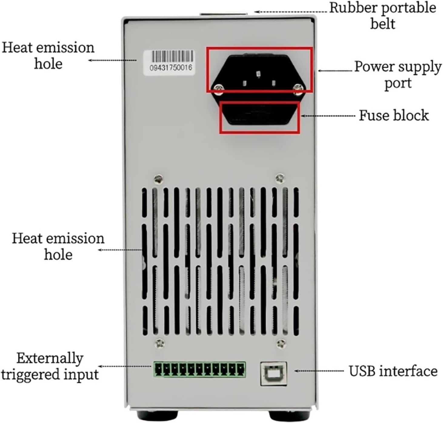
Figure 2.1: Rear panel of the ET5420A, highlighting the power supply port, fuse block, heat emission holes, and USB interface.
2.3 Power Connection
- Locate the power supply port on the rear panel of the ET5420A.
- Connect the provided power cord to the power supply port.
- Plug the other end of the power cord into a suitable AC power outlet.
- Ensure the power switch (usually located near the power port or on the front panel) is in the OFF position before connecting to power.
2.4 USB Interface Connection (Optional)
For remote operation and software communication, connect the ET5420A to a computer using a USB cable. The USB interface is located on the rear panel.
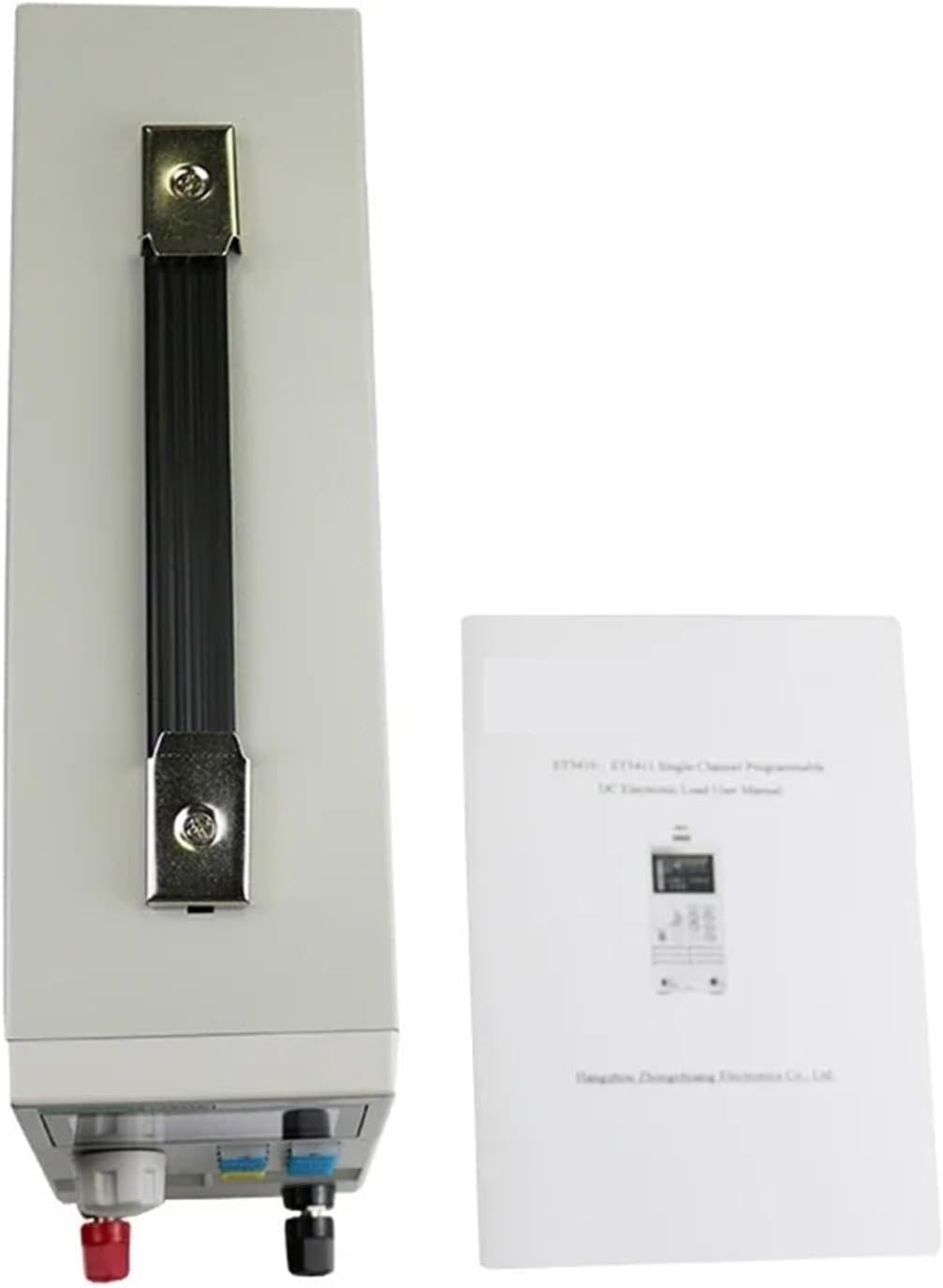
Figure 2.2: The ET5420A connected to a computer, enabling USB communication for remote control and data management.
2.5 Initial Power On
After ensuring all connections are secure, switch the power button to the ON position. The 2.8-inch TFT LCD screen will illuminate, displaying the startup sequence and then the main measurement interface.
3. Operation
3.1 Front Panel Overview

Figure 3.1: Front panel of the ET5420A, displaying the dual-channel measurement interface with voltage, current, and power readings, along with control buttons.
The front panel features the 2.8-inch TFT LCD display, navigation buttons, function keys, and input terminals for connecting the device under test.
3.2 Basic Navigation and Key Functions
- ESC: Exits the current menu or cancels an operation.
- ENT: Confirms a selection or enters a value.
- MODE: Cycles through different operating modes.
- MENU: Accesses the main menu for settings and configurations.
- SET: Enters parameter setting mode.
- CH: Selects between Channel 1 (CH1) and Channel 2 (CH2) for dual-channel models.
- ON/OFF: Toggles the load on or off.
- Lock/Unlock: Locks or unlocks the keypad to prevent accidental changes.
- Rotary Knob: Used for adjusting values and navigating menus.
3.3 Measurement Modes
The ET5420A supports various measurement modes, accessible via the MODE button or the menu system.
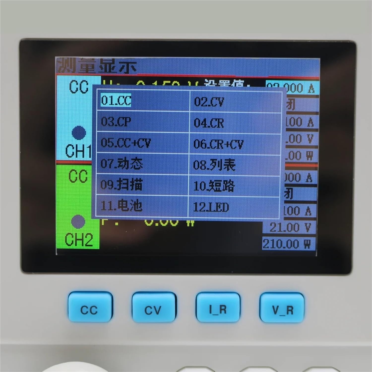
Figure 3.2: Display showing the selection menu for various measurement modes, including CC, CV, CR, CP, and specialized tests.
3.3.1 Basic Modes
- CC (Constant Current): Maintains a constant current regardless of voltage changes.
- CV (Constant Voltage): Maintains a constant voltage regardless of current changes.
- CR (Constant Resistance): Maintains a constant resistance.
- CP (Constant Power): Maintains a constant power.
- CC+CV: Combines constant current and constant voltage modes.
- CR+CV: Combines constant resistance and constant voltage modes.
3.3.2 Professional Modes
- Battery Test Mode: For capacity testing of various battery types.
- LED Test Mode: Simulates LED power supply performance.
- Tran Test Mode: Tests dynamic output performance of power supplies.
- Scan Test Mode: Tests power output continuity within a specified range.
- List Test Mode: Simulates various loading status changes.
- Short Circuit Test Mode: Simulates load short circuit conditions.
- Battery/Power Internal Resistance Test: Measures internal resistance.
- Conformity Testing Function: For compliance verification.
3.4 Remote Operation
The ET5420A can be controlled remotely via a USB connection to a computer. Install the provided software (or download the latest version from the manufacturer's website) to establish communication. This allows for advanced control, data logging, and automation of test sequences.
4. Maintenance
4.1 Cleaning
To clean the unit, disconnect it from all power sources and loads. Use a soft, dry cloth to wipe the exterior. For stubborn dirt, a slightly damp cloth with a mild detergent can be used, ensuring no liquid enters the device. Do not use abrasive cleaners or solvents.
4.2 Fuse Replacement
If the unit fails to power on or experiences unexpected power issues, the fuse may need replacement. The fuse block is located on the rear panel, adjacent to the power supply port. Always replace the fuse with one of the same type and rating as specified in the specifications section or on the unit itself.
4.3 General Care
- Avoid exposing the unit to extreme temperatures, humidity, or direct sunlight.
- Do not block the heat emission holes to ensure proper cooling.
- Handle the unit with care to prevent physical damage.
5. Troubleshooting
| Problem | Possible Cause | Solution |
|---|---|---|
| Unit does not power on. | No power supply; Blown fuse; Power cable not connected. | Check power cable connection; Verify power outlet; Replace fuse if necessary (refer to Section 4.2). |
| Incorrect readings or unstable operation. | Improper connection to load; Incorrect mode selection; Overload condition. | Ensure secure load connections; Select appropriate measurement mode; Check for overcurrent/overvoltage protection activation. |
| Overload protection activated. | Current, voltage, or power exceeds set limits. | Reduce the load; Adjust overcurrent/overvoltage/overpower protection parameters in the settings menu. |
| Input polarity reverse prompt. | Load connected with reversed polarity. | Immediately disconnect the load and correct the polarity of the input connection. |
| Remote control not working. | USB cable not connected; Driver not installed; Software issue. | Verify USB connection; Install necessary drivers; Restart software and device. |
6. Specifications
| Parameter | Value |
|---|---|
| Model | ET5420A |
| Input Voltage Range | 0-150V |
| Input Current Range | 0-20A per channel (Dual-Channel) |
| Max Power | 400W |
| Display | 2.8-inch TFT LCD |
| Resolution | 1mV / 1mA |
| Measurement Modes | CC, CV, CR, CP, CC+CV, CR+CV, Battery, LED, Tran, Scan, List, Short Circuit, Internal Resistance, Conformity Testing |
| Connectivity | USB Interface |
| Protection Features | Overcurrent, Overvoltage, Overpower, Overtemperature, Input Polarity Reverse |
| Item Weight | 10 Grams |
| Number of Pieces | 1 |
7. Warranty and Support
For warranty information and technical support, please refer to the documentation provided with your purchase or contact the manufacturer, LSLSL, directly. Keep your proof of purchase for any warranty claims.
Manufacturer: LSLSL