
Introduction
This manual provides detailed instructions for the installation, operation, and maintenance of the RYRMCVPVCT JK BMS PB2A16S15P Smart Inverter Battery Management System. This advanced BMS is designed for 8S-16S LiFePO4, Li-ion, and LTO battery packs, offering a 150A continuous charge/discharge current and active balancing capabilities. It integrates comprehensive protection features and various communication interfaces for efficient energy storage management.
Key features include active cell balancing, overcharge protection, over-discharge protection, overcurrent protection, short circuit protection, and temperature protection. The system supports Bluetooth, RS232, RS485, and CAN communication for monitoring and configuration via a dedicated mobile application or other compatible devices.
Product Overview
The JK BMS PB2A16S15P is a smart inverter BMS designed for robust battery management in energy storage applications. It ensures the longevity and safety of your battery pack through precise monitoring and control.

Figure 1: Overview of the JK-PB2A16S15P BMS board and 3.2-inch LCD display, highlighting key specifications such as BT/RS232/RS485/CAN/HEAT functions, Inverter BMS type, 2A balancing current, 8S-16S battery strings, 150A charge/discharge current, 300*100*18mm size, and Li-ion/Lifepo4/LTO battery type compatibility.
The system comprises the main BMS board and a 3.2-inch LCD display for real-time data visualization. It supports a wide range of battery configurations from 8S to 16S and is compatible with Li-ion, LiFePO4, and LTO battery chemistries.
Setup and Installation
Proper installation is crucial for the safe and efficient operation of the BMS. Always ensure the battery pack is disconnected before beginning installation.
1. Wiring Connections
- Battery Cell Connections: Connect the balance wires from each battery cell to the corresponding ports on the BMS. Ensure correct polarity and sequence (B0, B1, B2... up to B16).
- Main Power Connections: Connect the main positive (B+) and negative (B-) terminals of the battery pack to the designated ports on the BMS.
- Load/Charger Connections: Connect the load and charger to the common charge/discharge port (P-) and the main positive (P+) terminal.
- Temperature Sensors: If applicable, connect external temperature sensors to the designated ports on the BMS.
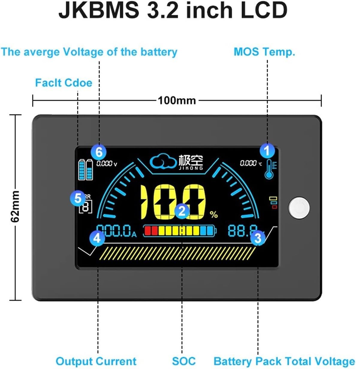
Figure 2: Angled view of the JK BMS PB2A16S15P main board, illustrating the various connection terminals for battery cells, main power, and communication interfaces. Ensure all connections are secure and correctly polarized.
2. LCD Display Connection
Connect the 3.2-inch LCD display to the dedicated display port on the BMS using the provided cable. Ensure the connection is firm.
3. Initial Power-Up and Configuration
- After all connections are made, power on the battery pack. The LCD display should illuminate.
- Download the official JK BMS mobile application from your device's app store.
- Enable Bluetooth on your mobile device and pair with the BMS.
- Use the app to verify battery parameters, cell voltages, and configure any necessary settings according to your battery pack specifications.
Operating Instructions
The JK BMS provides real-time monitoring and control through its 3.2-inch LCD display and mobile application.
1. LCD Display Interface

Figure 3: Detailed view of the JK BMS 3.2-inch LCD display. Key indicators include: 1. MOS Temp. (MOSFET Temperature), 2. SOC (State of Charge percentage), 3. Battery Pack Total Voltage, 4. Output Current, 5. Fault Code (Error indicator), and 6. Average Voltage of the Battery.
- MOS Temp.: Displays the temperature of the MOSFETs, critical for thermal management.
- SOC (State of Charge): Indicates the remaining battery capacity as a percentage.
- Battery Pack Total Voltage: Shows the overall voltage of the entire battery pack.
- Output Current: Displays the current flowing in or out of the battery pack.
- Fault Code: An indicator for system errors or warnings. Refer to the app or a detailed fault code list for specific meanings.
- Average Voltage of the Battery: Shows the average voltage across all connected cells.
2. Mobile Application Monitoring
The JK BMS mobile application provides a more detailed view of battery parameters, including individual cell voltages, temperature readings, historical data, and advanced settings. Use the app for:
- Real-time monitoring of all battery parameters.
- Adjusting protection thresholds (e.g., over-voltage, under-voltage).
- Enabling/disabling specific functions.
- Firmware updates (if available).
Maintenance
Regular maintenance ensures the longevity and optimal performance of your BMS and battery system.
- Visual Inspection: Periodically inspect all wiring and connections for signs of wear, corrosion, or looseness. Ensure all terminals are secure.
- Cleanliness: Keep the BMS and surrounding area clean and free from dust, dirt, and moisture. Use a dry, soft cloth for cleaning.
- Firmware Updates: Check the mobile application regularly for available firmware updates to ensure your BMS has the latest features and bug fixes.
- Environmental Conditions: Ensure the BMS operates within its specified temperature and humidity ranges to prevent damage.
Troubleshooting
This section addresses common issues you might encounter with the JK BMS.
| Problem | Possible Cause | Solution |
|---|---|---|
| BMS not powering on / LCD blank | Incorrect main power connection, loose cable, or battery pack discharged. | Verify main battery connections (B+, B-). Check battery pack voltage. Ensure LCD cable is securely connected. |
| Battery not charging/discharging | Overcharge/over-discharge protection activated, overcurrent protection, or temperature protection. | Check battery voltage and current on the LCD or app. Allow battery to cool if temperature is high. Verify charger/load connections. Reset BMS if necessary (refer to app for option). |
| Cell voltage imbalance | Normal operation (active balancing in progress) or significant cell degradation. | Allow the active balancing function to work. If imbalance persists or is severe, inspect individual cells for health. |
| Bluetooth connection issues | Bluetooth disabled on phone, app not updated, or interference. | Ensure Bluetooth is enabled on your device. Restart the app and BMS. Try pairing again. Reduce distance to BMS. |
| Fault Code displayed | Specific error detected by the BMS. | Refer to the JK BMS mobile application for a detailed explanation of the fault code and recommended actions. |
Technical Specifications
| Feature | Specification |
|---|---|
| Model | PB2A16S15P |
| BMS Type | Smart Inverter BMS |
| Battery String Compatibility | 8S-16S |
| Battery Type Compatibility | LiFePO4, Li-ion, LTO |
| Max Continuous Charge Current | 150A |
| Max Continuous Discharge Current | 150A |
| Active Balance Current | 0.6A - 2A (depending on configuration) |
| Charge and Discharge Port | Common Port |
| Communication Interfaces | Bluetooth (BT), RS232, RS485, CAN |
| Display | 3.2-inch LCD |
| Protection Functions | Overcharge, Over-discharge, Overcurrent, Short Circuit, Temperature Protection |
| Coulometer | Supported |
| Parallel Charging Current Limiting | 10A |
| Dimensions (BMS Board) | 300mm x 100mm x 18mm (approximate, from image) |
| Item Weight | 1000 Grams |
Warranty Information
Specific warranty details for the RYRMCVPVCT JK BMS PB2A16S15P are not provided in the product data. Please refer to the product packaging or contact the seller/manufacturer directly for warranty terms and conditions.
Customer Support
For technical assistance, troubleshooting beyond this manual, or inquiries regarding your RYRMCVPVCT JK BMS PB2A16S15P, please contact your point of purchase or the manufacturer's customer support channels. Contact information is typically available on the product packaging or the manufacturer's official website.