1. Introduction
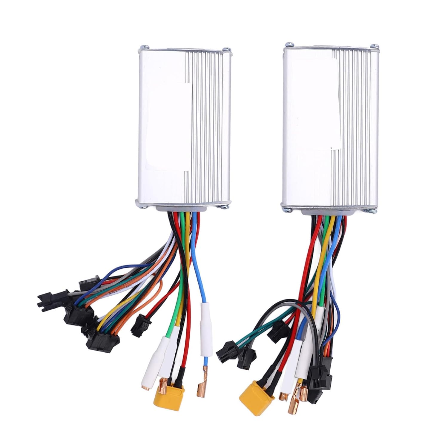
This manual provides essential instructions for the safe and effective use of your ICRPSTU Dual Drive Motor Controller. This kit includes both front and rear drive controllers, designed for 48V, 25A, and 1200W systems, supporting speeds up to 60 KM/H depending on your motor's specifications. It is compatible with various electric bicycles and scooters, offering precise power output management for enhanced efficiency and safety.
Please read this manual thoroughly before installation and operation to ensure proper function and to prevent damage to the product or injury.
2. Safety Information
Warning: Failure to follow these safety instructions may result in electric shock, fire, and/or serious injury.
- Always disconnect power before installing, removing, or servicing the controller.
- Ensure all connections are secure and correctly polarized to prevent short circuits.
- Do not expose the controller to water or extreme humidity.
- Avoid operating the controller outside its specified voltage and current ratings (48V, 25A, 1200W).
- Installation should ideally be performed by a qualified technician to ensure correct wiring and configuration.
- Keep children and pets away from electrical components.
- This controller is not compatible with dual drive controllers from other brands.
3. Package Contents
The following items are included in your package:
- 1 x Front Drive Controller
- 1 x Rear Drive Controller

4. Specifications
| Feature | Detail |
|---|---|
| Item Type | Electric Bike Controller |
| Brand | ICRPSTU |
| Model Number | ICRPSTU8e6tx1w9fc |
| Material | Aluminum Alloy + PCB |
| Voltage | 48V |
| Current | 25A |
| Power | 1200W |
| Max Speed Support | Up to 60 KM/H (dependent on motor) |
| Compatibility | Electric Bicycles, Electric Scooters |
| Package Dimensions | 8.66 x 5.12 x 2.36 inches |
| Item Weight | 15.1 ounces |
5. Setup and Installation
The ICRPSTU Dual Drive Motor Controller is designed for straightforward installation. However, due to the electrical nature of the product, professional installation is recommended to ensure safety and optimal performance.
5.1 General Installation Steps
- Power Disconnection: Before beginning any installation, ensure the power source to your electric bike or scooter is completely disconnected.
- Identify Components: Locate the existing motor controller(s) and the wiring harness for your electric vehicle.
- Mounting: Securely mount the new front and rear drive controllers in a suitable location, ensuring they are protected from physical damage and moisture. The aluminum alloy construction provides robustness.
- Wiring Connections: Carefully connect the wires from the controllers to the corresponding components of your electric bike/scooter. This typically includes connections for:
- Motor phases (usually three thick wires)
- Hall sensors (usually five thinner wires)
- Battery power (positive and negative)
- Throttle
- Brake levers
- Display/Control panel
- Other accessories (e.g., lights)
Refer to your electric bike/scooter's wiring diagram for specific connection details. Ensure all connectors are fully seated and locked.
- Initial Power-Up: Once all connections are verified, carefully reconnect the power source. Perform a low-speed test to ensure proper function before full operation.
Important Note: This dual drive controller system is designed to work together. It is not compatible with dual drive controllers from other brands. Attempting to mix and match components may lead to malfunction or damage.


6. Operating Instructions
Once the ICRPSTU Dual Drive Motor Controllers are correctly installed and connected, operation is typically managed through your electric bike or scooter's existing control system (e.g., display panel, throttle). The controllers manage the power delivery to the motors based on your input.
- Power On: Turn on your electric bike/scooter's main power switch. The controllers will initialize.
- Throttle Control: Use the throttle to control the speed and acceleration of your vehicle. The dual controllers will synchronize to provide smooth and powerful acceleration from both the front and rear motors.
- Braking: Engage the brake levers as usual. The controllers are designed to cut power to the motors when brakes are applied, enhancing safety.
- Monitoring: If your vehicle has a display, monitor battery level, speed, and other relevant parameters during operation.
The dual drive system provides enhanced performance and traction, especially beneficial for varied terrains and higher speeds. The precise power management ensures an efficient and stable ride.
7. Maintenance
The ICRPSTU Dual Drive Motor Controllers are built with robust aluminum alloy and PCB materials for durability and stability. Minimal maintenance is required, but adhering to these guidelines will help prolong the lifespan of your controllers:
- Keep Clean: Periodically clean the exterior of the controllers to remove dust, dirt, and debris. Use a dry, soft cloth. Do not use liquid cleaners directly on the unit.
- Inspect Connections: Regularly check all wiring connections to ensure they remain secure and free from corrosion. Loose connections can lead to intermittent power or component damage.
- Avoid Overheating: Ensure the controllers have adequate ventilation. While designed for heat dissipation, prolonged operation in extremely hot environments or under heavy load without proper airflow can affect performance.
- Protect from Moisture: Although robust, avoid direct exposure to heavy rain or submersion in water. Ensure the mounting location offers reasonable protection from the elements.
- Storage: If storing your electric vehicle for an extended period, ensure the controllers are kept in a dry, temperate environment.
8. Troubleshooting
If you encounter issues with your ICRPSTU Dual Drive Motor Controllers, consider the following troubleshooting steps:
| Problem | Possible Cause | Solution |
|---|---|---|
| No power to motors | Loose battery connection, faulty power switch, discharged battery, controller malfunction. | Check battery connections and charge level. Verify power switch functionality. Inspect controller wiring. |
| Motors not responding to throttle | Loose throttle connection, faulty throttle, Hall sensor issue, controller malfunction. | Check throttle wiring. Test throttle functionality. Inspect Hall sensor connections. |
| Intermittent power or erratic behavior | Loose wiring connections, moisture ingress, overheating. | Inspect all connections for tightness and corrosion. Ensure controllers are dry and have adequate ventilation. |
| One motor not working in dual drive setup | Faulty controller for that motor, wiring issue to that motor, motor problem. | Verify connections to the non-working motor's controller. Check the motor itself. |
| Controller gets excessively hot | Overload, insufficient ventilation, internal short. | Reduce load. Ensure proper airflow around the controller. If overheating persists, discontinue use and seek professional inspection. |
If these steps do not resolve the issue, it is recommended to consult a qualified electric vehicle technician or contact ICRPSTU customer support for further assistance.
9. Warranty and Support
For warranty information or technical support regarding your ICRPSTU Dual Drive Motor Controller, please refer to the documentation provided at the time of purchase or contact ICRPSTU customer service directly. Ensure you have your model number (ICRPSTU8e6tx1w9fc) and purchase details available when seeking support.