DIBTEBB xion23xx
DIBTEBB X99 Motherboard User Manual
Model: xion23xx
1. Product Overview
This manual provides detailed instructions for the installation, operation, and maintenance of the DIBTEBB X99 TPM Computer Motherboard. This motherboard is designed for high-performance computing, featuring an LGA 2011-3 socket, DDR4 quad-channel memory support, NVME NGFF M.2 compatibility, and an X99 C612 chipset.

Figure 1.1: Top-down view of the DIBTEBB X99 Motherboard, showcasing its layout with the CPU socket, RAM slots, and various connectors.
2. Package Contents
Upon opening the package, verify that all components are present and undamaged. The standard package includes:
- DIBTEBB X99 Motherboard
- Heatsink Adapter
- SATA Cable
If any items are missing or damaged, please contact your vendor immediately.
3. Key Features
The DIBTEBB X99 Motherboard offers a range of features designed for robust performance:
- LGA 2011-3 Socket: Supports compatible Intel processors.
- Power Connectors: Equipped with standard 8-pin and 24-pin power connectors for stable power delivery.
- Solid-State Capacitors: Utilizes all-solid-state capacitors for enhanced stability and durability.
- NVME NGFF M.2 Compatibility: Supports high-speed M.2 storage devices.
- DDR4 Quad-Channel Memory: Provides high bandwidth and lower power consumption compared to DDR3, ensuring system stability under load.

Figure 3.1: Visual representation of the motherboard highlighting key features such as LGA2011-3 socket, TPM 2.0 interface, DDR4 quad-channel support, NVME NGFF M.2, and X99 C612 chip.

Figure 3.2: Close-up view emphasizing the DDR4 Quad-Channel memory slots, designed for improved speed and energy efficiency.
4. Component Identification
Familiarize yourself with the various ports and connectors on the motherboard before installation.
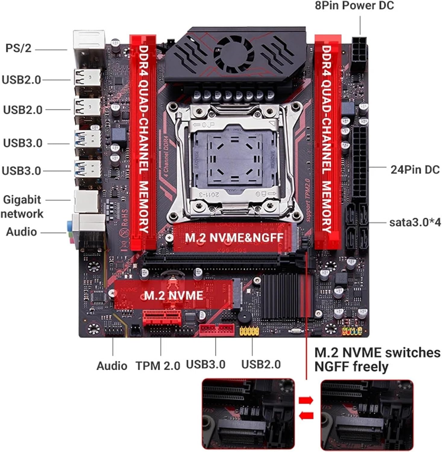
Figure 4.1: Detailed diagram of the motherboard indicating the location of various ports including PS/2, USB 2.0, USB 3.0, Gigabit network, Audio jacks, 8-pin and 24-pin power connectors, SATA 3.0 ports, M.2 NVME, and M.2 NVME/NGFF switch.

Figure 4.2: Close-up view of the rear I/O panel, showing the PS/2 ports, USB 2.0 ports, USB 3.0 ports, Gigabit Ethernet port, and audio jacks.
Front Panel Connectors
- Front USB: Ensure the front USB connector is inserted correctly into the designated yellow pin position on the motherboard. Incorrect insertion may prevent the computer from booting.
- Power Outlet: The motherboard requires both an 8-pin and a 24-pin power connector from the power supply unit (PSU).
5. Setup and Installation
Follow these steps carefully to install your DIBTEBB X99 Motherboard into your computer system.
5.1. Pre-Installation Checklist
- Ensure you have a compatible CPU (LGA 2011-3 socket).
- Prepare your computer case with adequate space and ventilation.
- Gather necessary tools: screwdriver, anti-static wrist strap (recommended).
- Unplug the power cord from your power supply unit before beginning installation.
5.2. Motherboard Installation
- Carefully place the motherboard into the computer case, aligning it with the standoffs.
- Secure the motherboard with screws.
- Install the CPU into the LGA 2011-3 socket. Ensure proper alignment and gently close the retention mechanism.
- Apply thermal paste to the CPU and install the CPU cooler/heatsink adapter.
- Install DDR4 memory modules into the quad-channel slots. Refer to the motherboard diagram for correct slot population.
- Connect the 24-pin ATX power connector and the 8-pin CPU power connector from your PSU to the motherboard.
- Connect SATA devices (e.g., hard drives, SSDs) using the provided SATA cables to the SATA 3.0 ports.
- Install NVME or NGFF M.2 SSDs into the designated M.2 slots.
- Connect front panel headers (USB, audio, power switch, reset switch, LED indicators) to their respective pins on the motherboard. Pay close attention to the front USB header (yellow pin) as incorrect connection can prevent booting.
- Install any expansion cards (e.g., graphics card) into the PCIe slots.
6. Operating Instructions
Once the motherboard and all components are installed, you can proceed with system operation.
6.1. Initial Boot-up
- Double-check all connections to ensure they are secure.
- Connect your monitor, keyboard, and mouse.
- Plug in the power cord to your PSU and turn on the power switch.
- Press the power button on your computer case.
- The system should power on and display the BIOS/UEFI screen.
6.2. BIOS/UEFI Configuration
Access the BIOS/UEFI setup by pressing the designated key (usually Del or F2) during boot-up. Here you can configure boot order, system time, and other hardware settings.
6.3. Operating System Installation
Install your preferred operating system (e.g., Windows, Linux) from a bootable USB drive or DVD. Follow the on-screen prompts for installation.
6.4. Driver Installation
After OS installation, install the necessary drivers for the motherboard chipset, network, audio, and any other integrated components. These are typically provided on a driver CD or can be downloaded from the manufacturer's website.
7. Maintenance
Proper maintenance ensures the longevity and stable operation of your motherboard.
- Dust Removal: Regularly clean dust from inside your computer case, especially from fans and heatsinks, using compressed air. Ensure the system is powered off and unplugged before cleaning.
- Temperature Monitoring: Monitor CPU and system temperatures to prevent overheating. Ensure proper airflow within the case.
- BIOS/UEFI Updates: Periodically check the manufacturer's website for BIOS/UEFI updates. Updates can improve compatibility, stability, and performance. Follow update instructions carefully to avoid system damage.
- Driver Updates: Keep your drivers updated to ensure optimal performance and compatibility with new software and hardware.
8. Troubleshooting
This section provides solutions to common issues you might encounter.
| Problem | Possible Cause | Solution |
|---|---|---|
| System does not boot / No display. |
|
|
| System powers on but no POST (Power-On Self-Test). |
|
|
| USB devices not recognized. |
|
|
For further assistance, consult the manufacturer's support resources or a qualified technician.
9. Specifications
| Feature | Detail |
|---|---|
| Brand | DIBTEBB |
| Model Name | xion23xx |
| Socket Type | LGA 2011-3 |
| Chipset | X99 C612chip |
| Memory Type | DDR4 Quad-Channel |
| Storage Interface | NVME NGFF M.2, SATA 3.0 |
| Power Connectors | 8-pin, 24-pin |
| Item Weight | 1.76 ounces (approx. 50 grams) |
| Package Dimensions | 1.18 x 0.79 x 0.39 inches |
| First Available Date | April 14, 2025 |
10. Warranty and Support
Information regarding product warranty and specific support contacts is not provided in the available product data. Please refer to the product packaging or the official DIBTEBB website for warranty details and customer support options.
For general inquiries or technical assistance, you may also contact your point of purchase.
Ask a question about this manual
Ask about setup, troubleshooting, compatibility, parts, safety, or missing instructions. Manuals+ will review the question and use this page’s manual context to help answer it.