YTGWLKCO BN44-00755A
YTGWLKCO BN44-00755A TV Power Supply Board Instruction Manual
Model: BN44-00755A, BN44-0075.5, BN4400755A, L55N4-ESM, PSLF281W07A REV1.3
1. Introduction
This instruction manual provides essential information for the YTGWLKCO BN44-00755A TV Power Supply Board. This component is designed to replace original power supply boards in compatible Samsung 50-inch and 55-inch televisions. It is crucial to read and understand this manual before attempting any installation or repair.
2. Product Overview
The BN44-00755A power supply board is a critical component responsible for converting household alternating current (AC) into direct current (DC) required by the television's internal circuits. It ensures stable power delivery to various TV components, including the main board, backlight, and audio circuits.
Key Features and Components:
- Basic Functions: Converts AC power to DC power for TV operation.
- Component Composition: Typically includes transformers, rectifiers, filters, and voltage regulators.
- Protection Function: Designed with overload, short circuit, and overheat protection to safeguard the TV.
- Circuit Design: Optimized for stable performance, affecting start-up time and energy consumption.
Compatible TV Models:
This power board is compatible with various Samsung 50-inch and 55-inch TV models, including but not limited to:
- UN50HU6900FXZA IS01
- UN50HU6950FXZA IS01, IS04, WS02
- UN50HU7000FXZA
- UN55HU6830FXZA KS02, ES01
- UN55HU6840FXZA KS02
- UN55HU6950FXZA TS01
- UE55HU6900, UE50HU6900
- UA50HU7000J, UA55HU7000J
Product Images:

Figure 1: Top view of the BN44-00755A power supply board, showing various components including capacitors, transformers, and heat sinks.
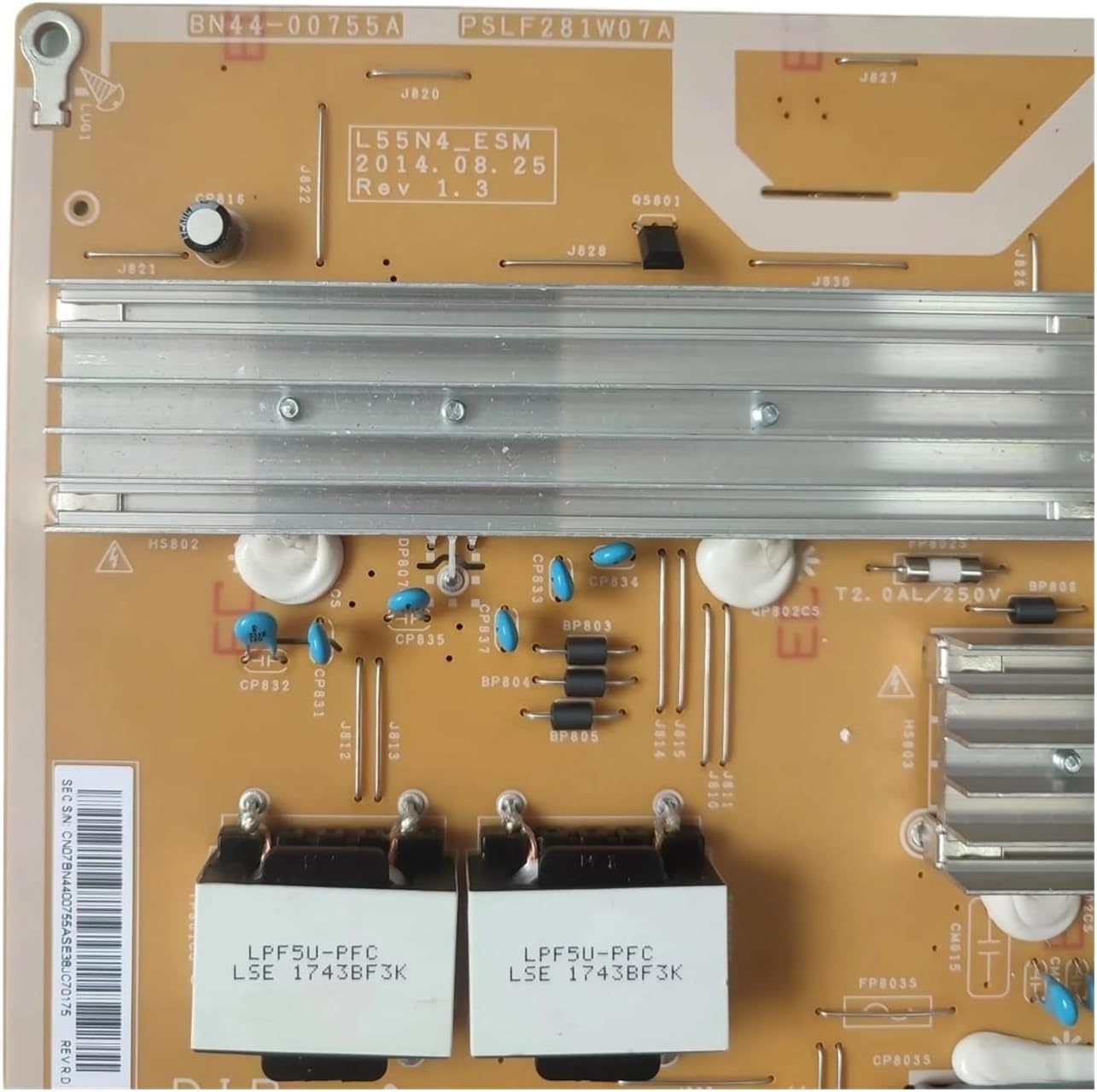
Figure 2: Close-up view of the power board, highlighting the model number BN44-00755A and revision details (L55N4-ESM, 2014.08.25 Rev 1.3).

Figure 3: Section of the power board showing input voltage specifications (100-240V~, 50/60Hz) and output voltage/current details for various rails (e.g., 5.3V, 12.8V, 17.5V, LED Driver Output).

Figure 4: Detailed view of the component side, showing various power inductors, capacitors, and integrated circuits.
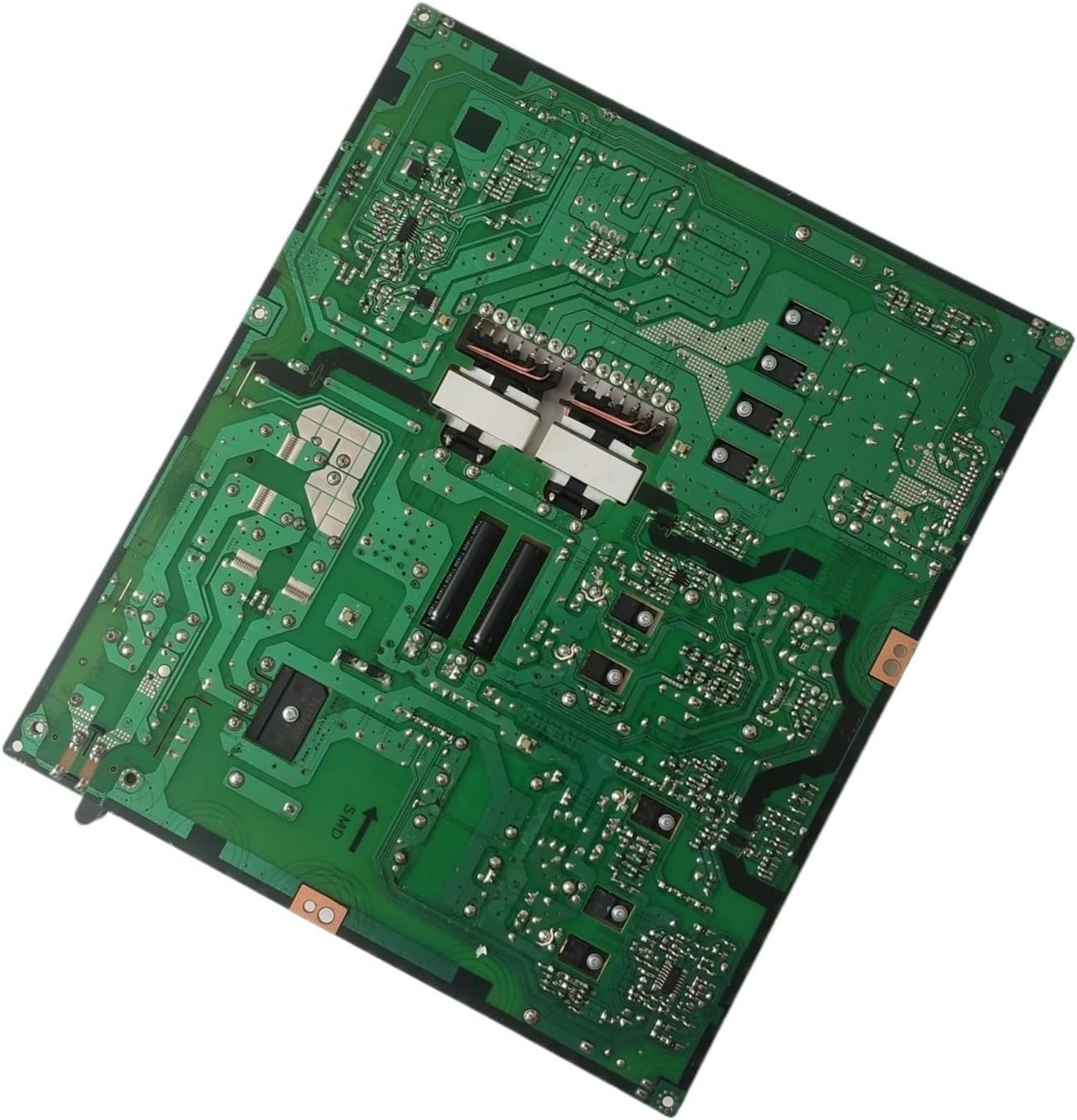
Figure 5: Underside view of the power board, revealing the printed circuit board (PCB) traces and solder points.
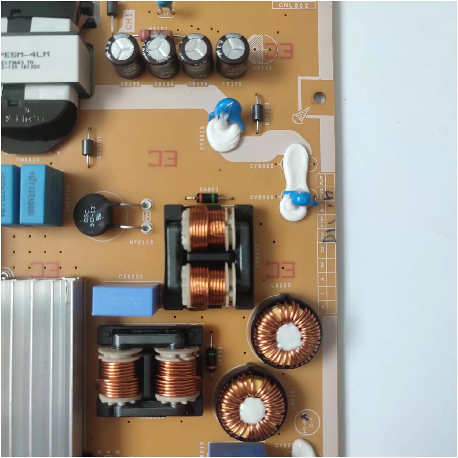
Figure 6: Close-up of inductors and capacitors on the power board, showing component markings.
3. Safety Information
WARNING: Working with television power supplies involves high voltages that can be lethal. Only qualified technicians should attempt installation or repair of this component. Always disconnect the television from the main power outlet and allow sufficient time for capacitors to discharge before handling the power board.
- Ensure the TV is unplugged from the wall outlet before beginning any work.
- Wear appropriate personal protective equipment, including insulated gloves and safety glasses.
- Use proper tools designed for electronic repair.
- Avoid touching exposed circuits or components while the TV is powered on or recently powered off.
- If you are unsure about any step, consult a professional television repair service.
4. Setup and Installation
Installation of a TV power supply board requires technical expertise and should ideally be performed by a certified technician. Incorrect installation can lead to further damage to the television or personal injury.
General Installation Steps (Professional Guidance Recommended):
- Preparation: Disconnect the TV from all power sources and external devices. Place the TV face down on a soft, clean surface to protect the screen.
- Access: Remove the back cover of the television to expose the internal components.
- Locate Old Board: Identify the existing power supply board. It is typically a large board with power input connections.
- Disconnect: Carefully disconnect all cables and connectors attached to the old power board. Note their positions or take photos for reference.
- Remove Old Board: Unscrew and remove the old power board from the TV chassis.
- Install New Board: Position the new BN44-00755A power board in place and secure it with the screws.
- Reconnect: Reconnect all cables and connectors to the new board, ensuring they are seated correctly and securely.
- Test: Before replacing the back cover, temporarily plug in the TV and perform a brief power-on test to ensure basic functionality.
- Reassemble: If the test is successful, unplug the TV again, replace the back cover, and secure all screws.
5. Operating Principles
Once installed, the power supply board operates automatically when the television is connected to a power source. It continuously regulates and supplies the necessary voltages to all internal circuits of the TV, enabling it to function correctly. There are no user-adjustable settings on the power board itself.
6. Maintenance
The BN44-00755A power supply board is designed for long-term reliability and typically requires no routine user maintenance. To ensure its longevity:
- Ensure adequate ventilation around the television to prevent overheating.
- Keep the TV and its internal components free from dust accumulation. Periodically clean the TV's vents with compressed air.
- Avoid exposing the television to extreme temperatures or humidity.
- Use a surge protector to safeguard against power fluctuations.
7. Troubleshooting
If your television experiences issues after replacing the power board, or if you suspect a power board malfunction, consider the following common faults and troubleshooting steps:
Common Faults Associated with Power Boards:
- No Power: The TV does not turn on at all, with no indicator lights.
- Flashing Indicator: The power indicator light flashes but the TV does not turn on.
- Turns Off After Starting: The TV powers on briefly, then shuts down.
- Intermittent Power: The TV randomly turns on and off.
General Troubleshooting Steps:
- Check Power Connection: Ensure the TV's power cord is securely plugged into a working wall outlet.
- Test Outlet: Plug another device into the same outlet to confirm it has power.
- Inspect Cables: Verify all internal cables connected to the power board are securely seated.
- Visual Inspection: With the TV unplugged, visually inspect the power board for any signs of damage, such as burnt components, bulging capacitors, or loose connections.
- Professional Diagnosis: If basic troubleshooting does not resolve the issue, it is recommended to seek assistance from a qualified technician for further diagnosis and repair.
8. Specifications
| Feature | Detail |
|---|---|
| Part Model | BN44-00755A (also known as BN44-0075.5, BN4400755A, L55N4-ESM, PSLF281W07A REV1.3) |
| Type | Power Supply Constant Current Integration (LIPS) |
| Input Voltage | 100-240V~, 50/60Hz, 2.9A (as per image) |
| Output Voltages | 5.3V / 1.0A, 12.8V / 1.0A, 17.5V / 0.8A (as per image) |
| LED Driver Output | 553V 450mA (as per image) |
| Compatible TV Sizes | 50/55 Inch Samsung TVs |
| Package Dimensions | 1.18 x 0.79 x 0.39 inches |
| Item Weight | 1.76 ounces |
9. Warranty and Support
Specific warranty details for this product are typically provided by the seller at the time of purchase. Please refer to your purchase documentation or contact the seller directly for information regarding warranty coverage and return policies.
For technical support or further assistance, it is recommended to consult a qualified television repair professional. The manufacturer, YTGWLKCO, does not provide direct end-user support for component-level repairs.
Related Documents - BN44-00755A
 |
Biuletyn Serwisowy: Schematy Zasilaczy i Inwerterów LCD Szczegółowe schematy zasilaczy i inwerterów dla telewizorów i monitorów LCD, obejmujące modele Samsung BN44-xxxxx, Sony, AOC, Thomson. Dokument zawiera wykazy układów scalonych i spisy chronologiczne/alfabetyczne. |
 |
Samsung QA55QN90AASXNZ (BA02) Exploded View and Parts List Detailed exploded view and parts list for the Samsung QA55QN90AASXNZ (BA02) television, including component identification and material codes. |
 |
Samsung KU6400 Series Exploded View and Parts List Detailed exploded views and comprehensive parts list for Samsung KU6400 series televisions, including part codes, descriptions, and quantities for efficient maintenance and repair. |
 |
Samsung TV Exploded View and Parts List A detailed parts list and exploded view diagram for Samsung televisions, including mechanical and electrical components, material codes, and specifications for various models like KU6000 and MU6100N. This document serves as a comprehensive guide for identifying TV parts. |
 |
Qoltec Power Adapter for Samsung Monitor 30W | 14V | 2.1A | 6.5*4.4 Plug Detailed product information for the Qoltec 30W power adapter designed for Samsung monitors, featuring 14V output, 2.1A current, and a 6.5*4.4mm plug. Includes technical specifications and safety features. |
 |
Samsung BN44-00428B Power Supply Unit (PSU) Schematic Diagram This document provides the schematic diagram for the Samsung BN44-00428B Power Supply Unit (PSU), detailing its Power Factor Correction (PFC) stage, standby circuit, main power conversion, and multiple LED driver circuits for display backlighting. |
Ask a question about this manual
Ask about setup, troubleshooting, compatibility, parts, safety, or missing instructions. Manuals+ will review the question and use this page’s manual context to help answer it.