1. Introduction
This manual provides essential instructions for the safe and efficient installation, operation, and maintenance of the HLTNC C30S RS485 AC Servo Motor and Driver Kit. This kit is designed for precise motion control in various industrial applications, particularly CNC machinery. Please read this manual thoroughly before using the product to ensure proper functionality and to prevent damage or injury.
2. Safety Instructions
Adherence to the following safety guidelines is crucial for preventing accidents and ensuring the longevity of the equipment.
- Electrical Safety: Ensure all power connections are made by qualified personnel. Disconnect power before performing any installation, maintenance, or inspection. The system operates at 220V AC; exercise extreme caution.
- Grounding: Properly ground the servo motor and driver to prevent electrical shock and ensure stable operation.
- Installation Environment: Install the kit in a clean, dry, and well-ventilated area, free from excessive dust, moisture, corrosive gases, and vibrations. Maintain appropriate operating temperatures.
- Mechanical Safety: Moving parts of the servo motor can cause injury. Ensure all mechanical connections are secure and that rotating parts are guarded if accessible during operation.
- Emergency Stop: Implement an accessible emergency stop system in your application design.
- Qualified Personnel: Only trained and authorized personnel should install, operate, and maintain this equipment.
3. Package Contents
Upon unpacking, verify that all components listed below are present and undamaged. If any items are missing or damaged, contact your supplier immediately.

Figure 3.1: Overview of the HLTNC AC Servo Motor and Driver Kit components. This image displays the AC servo drive, the AC servo motor, various connection cables (power, encoder, control), and additional accessories such as resistors and connectors.
- AC Servo Motor (400W or 750W variant)
- AC Servo Driver (C30S RS485)
- 3-meter Power Cable
- 3-meter Encoder Cable
- Control Cable
- Associated Connectors and Resistors
- Instruction Manual (this document)
4. Product Overview
4.1. AC Servo Motor
The AC Servo Motor is a high-precision rotary actuator designed for dynamic and accurate positioning. It features an absolute encoder for precise feedback and control. Available in 400W and 750W configurations, both offering 3000 RPM.
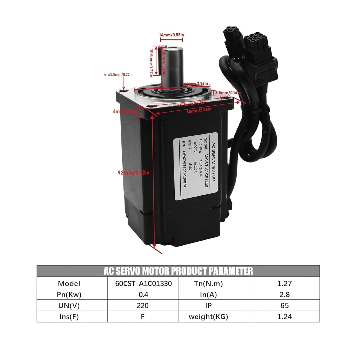
Figure 4.1.1: Dimensions and key parameters for the 400W AC Servo Motor (Model 60CST-A1C01330). This image details the physical dimensions in millimeters and inches, along with a table showing power (Pn), rated torque (Tn), rated current (In), rated voltage (UN), insulation class (Ins), IP rating, and weight.

Figure 4.1.2: Dimensions and key parameters for the 750W AC Servo Motor (Model 80CST-A1C02430). This image provides physical dimensions in millimeters and inches, and a table outlining power (Pn), rated torque (Tn), rated current (In), rated voltage (UN), insulation class (Ins), IP rating, and weight.
4.2. AC Servo Driver (C30S RS485)
The C30S RS485 AC Servo Driver is responsible for controlling the servo motor's speed, position, and torque. It features an RS485 communication interface for integration into control systems, offering precise and reliable performance.

Figure 4.2.1: Dimensions and key parameters for the AC Servo Drive (Model HTNC-C30S-L15A-RABN-B). This image shows the physical dimensions in millimeters and inches, along with a table detailing the model, phase, frequency, maximum current, voltage, and weight.

Figure 4.2.2: Dimensions and key parameters for the AC Servo Drive (Model HTNC-C30S-L20A-RABN-B). This image provides physical dimensions in millimeters and inches, and a table outlining the model, phase, frequency, maximum current, voltage, and weight.
5. Specifications
5.1. General Product Specifications
| Feature | Description |
|---|---|
| Brand | DMMRUTXB |
| Model Name | C30S RS485 Driver Kit |
| Motor Power Options | 400W, 750W |
| Rated Speed | 3000 RPM |
| Rated Torque (400W) | 1.3 N.m |
| Rated Torque (750W) | 2.4 N.m |
| Input Voltage | 220V AC |
| Encoder Type | Absolute Encoder |
| Communication Interface | RS485 |
| Cable Length | 3 meters (Power & Encoder) |
5.2. Detailed Motor Specifications
Refer to Figure 4.1.1 and Figure 4.1.2 for detailed dimensions and parameters of the 400W and 750W servo motors, respectively.
5.3. Detailed Driver Specifications
Refer to Figure 4.2.1 and Figure 4.2.2 for detailed dimensions and parameters of the AC servo drives.
6. Setup and Installation
Proper installation is critical for the performance and safety of the servo system. Ensure all power is disconnected before proceeding.
6.1. Mounting
- Servo Motor: Mount the servo motor securely to the mechanical load using appropriate fasteners. Ensure proper alignment to prevent excessive vibration and wear.
- Servo Driver: Mount the servo driver in an enclosure that provides adequate ventilation and protection from environmental factors. Allow sufficient space for heat dissipation.
6.2. Wiring Diagram
The following diagram illustrates the typical wiring connections between the AC Servo Motor, AC Servo Drive, an interface board, and a computer. Ensure all connections are firm and correct according to the diagram.

Figure 6.2.1: Detailed wiring diagram for the HLTNC AC Servo Motor and Driver Kit. This diagram shows the connections from the computer to an interface board, then to the AC Servo Drive, and finally to the AC Servo Motor via control, encoder, and power cables. Specific terminals for D-P, P+, D+, U, V, W, PE are indicated.
- Power Cable: Connect the 3-meter power cable from the servo motor to the designated power output terminals (U, V, W, PE) on the servo drive. Ensure correct phase sequence.
- Encoder Cable: Connect the 3-meter encoder cable from the servo motor's encoder port to the corresponding encoder input on the servo drive. This provides feedback for precise control.
- Control Cable: Connect the control cable from your CNC interface board (or control system) to the control input port on the servo drive. This typically includes RS485 communication lines (D-P, P+, D+) and other control signals.
- Grounding: Ensure all components are properly grounded to a common ground point.
7. Operating Instructions
After successful installation and wiring, follow these steps for initial power-up and basic operation.
- Pre-Power Check: Double-check all wiring connections for correctness and security. Ensure no loose wires or short circuits.
- Power On: Apply 220V AC power to the servo drive. Observe the indicator lights on the drive for normal operation status.
- Parameter Configuration: Using the RS485 interface and appropriate software (provided separately or available from manufacturer), configure the servo drive parameters according to your application's requirements. This includes motor type, encoder resolution, control modes (position, speed, torque), and tuning parameters.
- Test Run: Perform a low-speed, no-load test run to verify motor rotation direction and basic control response. Gradually increase speed and load as confidence in system stability grows.
- Monitoring: Continuously monitor the motor and drive for unusual noises, excessive heat, or erratic behavior during initial operation.
For detailed parameter settings and advanced control, refer to the specific software manual for the C30S RS485 driver.
8. Maintenance
Regular maintenance helps ensure optimal performance and extends the lifespan of your servo system.
- Cleaning: Periodically clean the servo motor and drive to remove dust and debris. Use a soft, dry cloth. Do not use solvents or abrasive cleaners. Ensure cooling fins on the drive are clear for proper heat dissipation.
- Connection Check: Regularly inspect all electrical and mechanical connections for tightness and signs of wear or corrosion. Re-tighten as necessary.
- Cable Inspection: Check cables for any signs of damage, fraying, or insulation degradation. Replace damaged cables immediately.
- Environmental Monitoring: Ensure the operating environment remains within specified temperature and humidity ranges.
- Bearing Inspection: Listen for unusual noises from the motor bearings. If abnormal noise is detected, consult a qualified technician.
Always disconnect power before performing any maintenance tasks.
9. Troubleshooting
This section provides solutions to common issues. For more complex problems, consult the detailed driver manual or contact technical support.
| Problem | Possible Cause | Solution |
|---|---|---|
| Motor does not move | No power to drive; incorrect wiring; emergency stop active; drive fault. | Check power supply; verify all wiring connections; release emergency stop; check drive status indicators for fault codes. |
| Motor vibrates excessively or makes unusual noise | Improper tuning parameters; mechanical misalignment; loose connections; motor overload. | Adjust PID gain or tuning parameters; check motor mounting and coupling alignment; inspect all connections; reduce load or verify motor sizing. |
| Drive displays a fault code | Overcurrent, overvoltage, undervoltage, encoder error, overheat. | Refer to the C30S RS485 driver manual for specific fault code interpretations and corrective actions. Address the underlying cause (e.g., check power, motor, encoder cable). |
| Loss of communication via RS485 | Incorrect wiring; wrong communication parameters (baud rate, parity); faulty cable; software issue. | Verify RS485 wiring (D-P, P+, D+); check communication settings in software; test cable continuity; restart software/computer. |
10. Warranty and Support
For warranty information and technical support, please refer to the documentation provided with your purchase or contact your vendor. Keep your purchase receipt as proof of purchase for warranty claims.
Manufacturer: DMMRUTXB


