1. Introduction
This manual provides essential instructions for the installation, operation, and maintenance of the Generic 880G1 SFF Main Board. Please read this manual thoroughly before proceeding with installation or use to ensure proper functionality and safety.
2. Safety Information
- Always disconnect power from your computer system before installing or removing any components.
- Wear an anti-static wrist strap or frequently touch a grounded metal object to discharge static electricity, which can damage sensitive electronic components.
- Handle the main board by its edges to avoid touching components or connectors.
- Ensure proper ventilation within your computer case to prevent overheating.
- Keep the main board away from liquids and extreme temperatures.
3. Package Contents
Verify that all items are present in your package. If any items are missing or damaged, contact your vendor.
- Generic 880G1 SFF Main Board
- (Optional) I/O Shield
- (Optional) SATA Data Cables
- (Optional) Driver CD/DVD or USB drive
4. Product Overview
The 880G1 SFF Main Board is designed for Small Form Factor (SFF) systems, providing a compact yet functional platform for your computing needs. Below is a general representation of a main board, highlighting common areas.
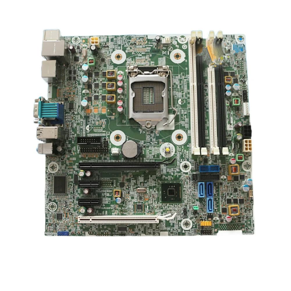
Figure 4.1: Generic 880G1 SFF Main Board. This image displays the overall layout of the motherboard, including various ports, slots, and components.
4.1 Key Components and Connectors
- CPU Socket: Area for installing the Central Processing Unit.
- RAM Slots: Slots for installing DDR memory modules.
- PCIe Slots: Expansion slots for graphics cards, network cards, etc.
- SATA Ports: Connectors for storage devices like HDDs and SSDs.
- USB Headers: Internal connectors for front panel USB ports.
- Front Panel Headers: Connectors for power button, reset button, LEDs.
- Power Connectors: Main ATX power (24-pin) and CPU power (4/8-pin).
- I/O Panel: External ports for USB, Ethernet, Audio, Video (VGA, DisplayPort, HDMI).
5. Setup and Installation
5.1 Preparing Your System
- Ensure your power supply is compatible with the main board's power requirements.
- Prepare your computer case by installing standoffs in the correct positions for the main board.
5.2 Installing the Main Board
- Carefully place the I/O shield into the rear opening of your computer case.
- Align the main board with the standoffs and gently lower it into the case.
- Secure the main board with screws, ensuring it is firmly seated but not overtightened.
5.3 Installing Components
- CPU Installation: Open the CPU socket lever, align the CPU with the socket (matching the triangle/arrow indicators), gently place it in, and close the lever. Apply thermal paste and install the CPU cooler.
- RAM Installation: Open the clips on the RAM slots, align the memory module notch with the slot key, and press down firmly on both ends until the clips snap into place.
- Storage Devices: Connect SATA data cables from the main board to your SSDs/HDDs. Connect power cables from the power supply to these devices.
- Power Connections: Connect the 24-pin ATX power cable and the 4/8-pin CPU power cable from your power supply to the main board.
- Front Panel Connections: Connect the power button, reset button, HDD LED, and power LED cables from your case to the corresponding pins on the main board's front panel header. Refer to the main board's silkscreen labels for correct orientation.
- Expansion Cards: If applicable, install graphics cards or other PCIe cards into the appropriate PCIe slots and secure them.
6. Operating Instructions
6.1 Initial Boot
- After all components are installed and connected, close your computer case.
- Connect your monitor, keyboard, and mouse to the appropriate I/O panel ports.
- Connect the power cord to your power supply and turn on the power supply switch.
- Press the power button on your computer case. The system should power on, and you should see output on your monitor.
6.2 BIOS/UEFI Configuration
During the initial boot sequence, press the designated key (commonly DEL, F2, F10, or F12) to enter the BIOS/UEFI setup utility. Here you can configure boot order, system time, and other hardware settings. Save changes before exiting.
6.3 Operating System Installation
Once the BIOS/UEFI is configured, you can proceed with installing your preferred operating system (e.g., Windows, Linux) from a bootable USB drive or DVD.
7. Maintenance
- Dust Removal: Regularly clean dust from inside your computer case using compressed air. Pay attention to CPU coolers, GPU fans, and case fans to ensure optimal airflow.
- Cable Management: Ensure cables are neatly routed to avoid obstructing airflow and to prevent accidental disconnections.
- BIOS/UEFI Updates: Periodically check the manufacturer's website for BIOS/UEFI updates, which can improve stability, compatibility, and performance. Follow update instructions carefully.
8. Troubleshooting
- No Power:
- Check if the power supply is connected and switched on.
- Verify all power cables (24-pin ATX, CPU power) are securely connected to the main board.
- Ensure the front panel power button cable is correctly connected to the main board.
- No Display:
- Ensure the monitor is connected to the correct video output (either integrated graphics on the main board or a dedicated graphics card).
- Reseat the RAM modules. Incorrectly seated RAM is a common cause of no display.
- If using a dedicated graphics card, reseat it in its PCIe slot and ensure its power connectors are attached.
- System Instability/Crashes:
- Check for overheating. Ensure CPU cooler and case fans are functioning.
- Run memory diagnostic tools to check for faulty RAM.
- Ensure all drivers (chipset, graphics, etc.) are up to date.
- BIOS/UEFI Reset: If you encounter issues after changing BIOS settings, you can clear the CMOS by removing the CMOS battery for a few minutes or using the CLR_CMOS jumper (refer to main board silkscreen for location).
9. Specifications
| Model Number | 796108-001/601, 717372-003 Q87 |
| Brand | Generic |
| Form Factor | SFF (Small Form Factor) |
| RAM (as per product data) | 111 KB (Note: This value may be a placeholder or refer to a specific component's memory, not system RAM capacity.) |
| Memory Type (as per product data) | EEPROM (Note: This typically refers to firmware storage, not system RAM type.) |
| ASIN | B0F4MRVFSJ |
Note: Specific CPU compatibility, chipset details, and exact memory types (e.g., DDR3, DDR4) are not provided in the available data. Please refer to the original system documentation for full compatibility details.
10. Warranty and Support
For warranty information and technical support, please contact your original vendor or the seller from whom you purchased this product. Keep your proof of purchase for any warranty claims.
For further assistance, you may also refer to online resources or community forums related to the 880G1 SFF Main Board for general troubleshooting tips and compatibility information.