ZLDRSLUZ AGC150 Core
AGC150 AGC 150 Generator Auto Start Control User Manual
Brand: ZLDRSLUZ | Model: AGC150 Core
1. Introduction
This manual provides detailed instructions for the installation, operation, and maintenance of the ZLDRSLUZ AGC150 AGC 150 Generator Auto Start Control. The AGC150 is an advanced electric control unit designed to automate the starting and stopping of generators, ensuring reliable power management.
Please read this manual thoroughly before attempting to install or operate the device. Retain this manual for future reference.
2. Product Overview
The AGC150 Core is a sophisticated generator control module featuring a user-friendly interface and robust connectivity options. It is engineered for precise control and monitoring of generator sets.
2.1 Front Panel Layout

Figure 2.1: Front view of the AGC150 control unit. This image displays the main screen showing power parameters (e.g., fixed power, voltage, frequency, power factor, kW, kVA, kvar) and various control buttons including power, navigation arrows (up, down, left, right, OK), and a return button. Below the screen, there are illuminated status indicators and a schematic representation of power flow.
- Display Screen: Shows operational data, settings, and alerts.
- Navigation Buttons: Used to scroll through menus and adjust settings (Up, Down, Left, Right, OK).
- Power Button: For turning the unit on or off.
- Status Indicators: LEDs indicating operational status, alarms, and power flow.
2.2 Rear Panel Connections
The rear panel houses all necessary terminals for power supply, sensor inputs, control outputs, and communication interfaces.
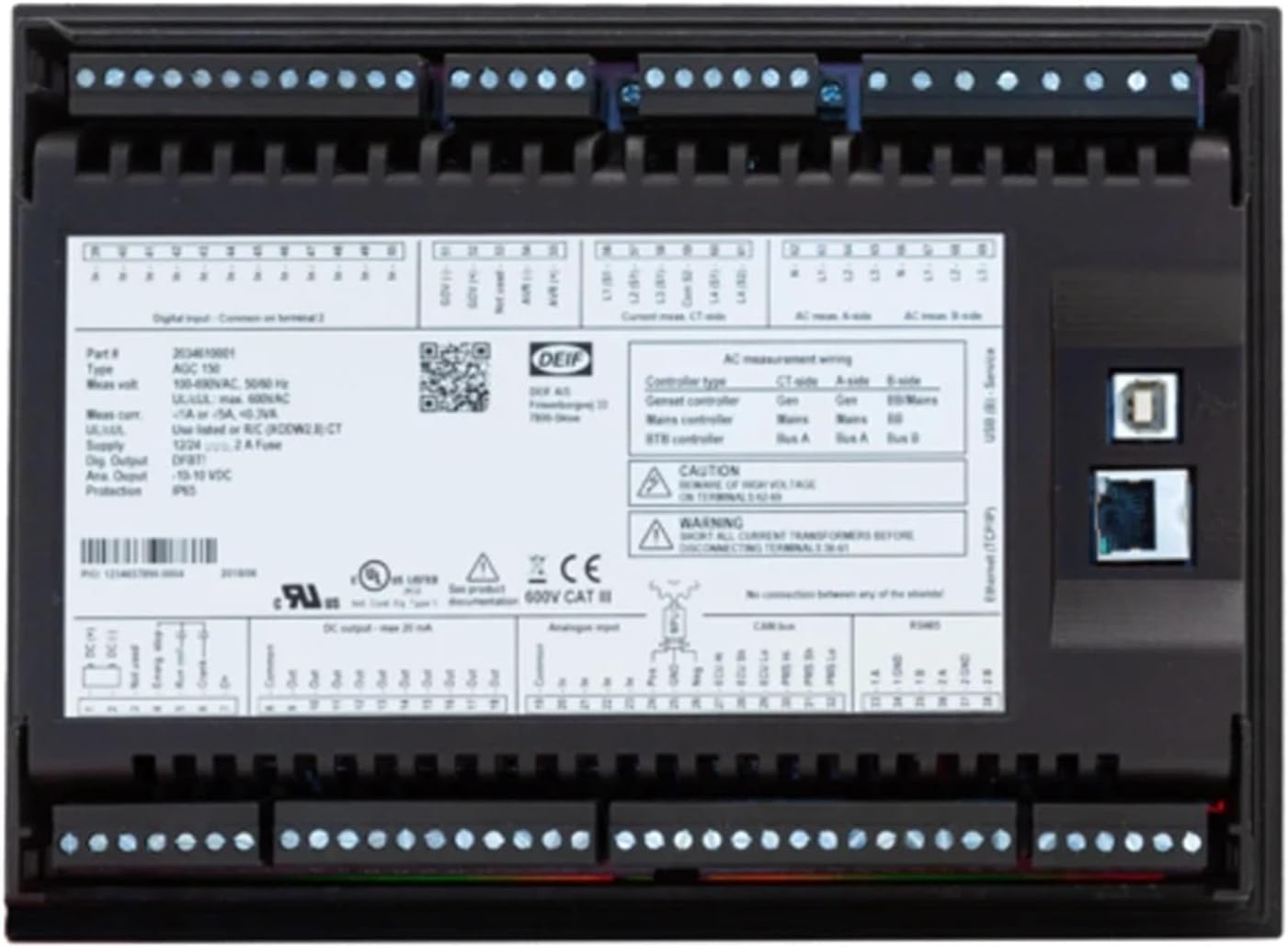
Figure 2.2: Rear view of the AGC150 control unit. This image shows the extensive array of terminal blocks for digital inputs, AC measurement wiring, and various control signals. Also visible are the USB and Ethernet ports for configuration and communication, along with product labels detailing specifications like voltage, current, and certifications.
- Terminal Blocks: For connecting power, generator inputs, mains inputs, and control signals.
- USB Port: For local configuration and firmware updates.
- Ethernet Port: For network communication and remote monitoring.
- CAN-Bus Port: For communication with other compatible devices.
3. Setup and Installation
Proper installation is crucial for the safe and reliable operation of the AGC150. Ensure all power is disconnected before beginning installation.
3.1 Mounting
- Select a suitable location for mounting the AGC150, ensuring it is protected from excessive moisture, dust, and vibration.
- Ensure adequate ventilation around the unit.
- Mount the unit securely using appropriate fasteners through the designated mounting holes.
3.2 Wiring Connections
Refer to the wiring diagram provided with your unit and the labels on the rear panel (Figure 2.2) for precise connections. Below are general guidelines:
- Power Supply: Connect the unit to a stable 12/24V DC power source. Ensure correct polarity.
- Generator Inputs: Connect the generator voltage and current transformer (CT) inputs to the designated terminals. Pay close attention to phase rotation and CT polarity.
- Mains Inputs: If applicable, connect the mains voltage and CT inputs.
- Digital Inputs: Connect various sensors and control signals (e.g., remote start/stop, emergency stop, oil pressure, water temperature) to the digital input terminals.
- Relay Outputs: Connect the control outputs (e.g., fuel solenoid, starter motor, breaker control) to the appropriate relays.
- Communication: Connect Ethernet or CAN-Bus cables for network integration if required.
WARNING: High voltage is present. All wiring should be performed by qualified personnel only. Disconnect all power sources before making any connections.
4. Operating Instructions
Once installed and wired correctly, the AGC150 is ready for operation.
4.1 Powering On/Off
- To power on the unit, press the Power button (usually indicated by a circle with a vertical line). The display will illuminate.
- To power off, press and hold the Power button until the unit shuts down.
4.2 Navigating the Menu
- Use the Up and Down arrow buttons to scroll through menu options.
- Use the Left and Right arrow buttons to navigate between screens or adjust values.
- Press the OK button to select an option or confirm a setting.
- Press the Return button (often an arrow curving left) to go back to the previous screen or exit a menu.
4.3 Auto Start/Stop Operation
The AGC150 is designed for automatic generator control. Once configured, it will automatically start the generator based on predefined conditions (e.g., mains failure, low battery voltage) and stop it when conditions are met (e.g., mains restored, load shed).
- Ensure all auto-start parameters are correctly set in the configuration menu.
- Monitor the display for current operational status and any active alarms.
5. Maintenance
Regular maintenance helps ensure the longevity and reliable performance of your AGC150 unit.
- Cleaning: Periodically clean the unit's exterior with a soft, dry cloth. Do not use abrasive cleaners or solvents.
- Connections: Annually inspect all wiring connections for tightness and signs of corrosion. Loose connections can lead to intermittent operation or damage.
- Firmware Updates: Check the manufacturer's website for available firmware updates. Updates can provide new features or improve performance.
- Environmental Check: Ensure the operating environment remains within specified temperature and humidity ranges.
6. Troubleshooting
This section provides solutions to common issues. For problems not listed here, contact technical support.
| Problem | Possible Cause | Solution |
|---|---|---|
| Unit does not power on. | No power supply; Incorrect wiring; Blown fuse. | Check DC power supply connections. Verify input voltage. Check the 2A fuse on the rear panel (Figure 2.2). |
| Generator does not start automatically. | Auto-start function disabled; Incorrect settings; Faulty input sensor. | Verify auto-start settings in the menu. Check status of relevant input sensors (e.g., mains status, battery voltage). |
| Display shows an error message. | System fault; Sensor error; Configuration issue. | Note the exact error message. Refer to the specific error code documentation (if available) or contact support with the error details. |
| Incorrect readings on display. | Incorrect CT wiring; Sensor calibration issue. | Verify CT connections and polarity. Check calibration settings in the menu. |
7. Specifications
Key technical specifications for the ZLDRSLUZ AGC150 Core Generator Auto Start Control:
| Parameter | Value |
|---|---|
| Model | AGC150 Core |
| Manufacturer Model Number | ZLDRSLUZ |
| Input Voltage (AC Measurement) | 100-690VAC, 50/60 Hz (UL/cUL max. 600VAC) |
| Supply Voltage (DC) | 12/24VDC |
| Fuse | 2A (on rear panel) |
| Item Weight | 1.76 ounces |
| Package Dimensions | 1.18 x 0.79 x 0.39 inches |
| ASIN | B0F4MM3WSB |
| Date First Available | April 12, 2025 |
8. Warranty and Support
For information regarding warranty coverage, technical support, or service, please contact the seller or the manufacturer, ZLDRSLUZ, directly. Keep your purchase receipt and product serial number (if applicable) handy when contacting support.
The manufacturer's contact information can typically be found on their official website or on the product packaging.
Ask a question about this manual
Ask about setup, troubleshooting, compatibility, parts, safety, or missing instructions. Manuals+ will review the question and use this page’s manual context to help answer it.