
1. Introduction
This manual provides comprehensive instructions for the safe and effective use of the Aicevoos AS-7199A Analog Multimeter. Please read this manual thoroughly before operating the device and retain it for future reference. The AS-7199A is a versatile pointer multimeter designed for various electrical measurements, including AC/DC voltage, DC current, resistance, and more.
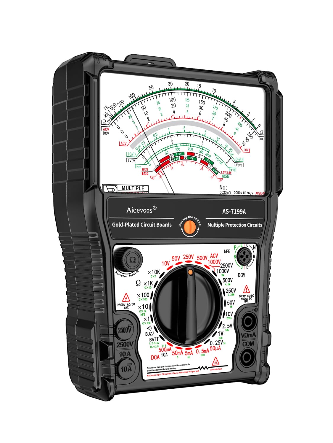
Figure 1: Aicevoos AS-7199A Analog Multimeter with test leads.
2. Safety Information
Always observe basic safety precautions when using this multimeter to reduce the risk of fire, electric shock, or personal injury.
- Do not exceed the maximum input values for any range.
- Use caution when working with voltages above 30V AC RMS, 42V peak, or 60V DC. These voltages pose a shock hazard.
- Inspect test leads for damaged insulation or exposed metal before use.
- Ensure the function switch is in the correct position for the desired measurement before connecting to the circuit.
- Do not operate the multimeter if it appears damaged or if the case is open.
- Replace batteries when the low battery indicator appears to ensure accurate readings.
3. Product Components
The Aicevoos AS-7199A Analog Multimeter package includes the following items:
- 1 x Aicevoos AS-7199A Analog Multimeter
- 1 x Pair of Test Leads with Protective Caps
- 1 x User Manual (this document)
- 2 x 1.5V Batteries (AAA type, typically)
4. Setup
4.1. Battery Installation
The multimeter requires two 1.5V batteries for operation.
- Locate the battery compartment cover on the back of the multimeter.
- Use a screwdriver (if necessary) to open the battery compartment.
- Insert the two 1.5V batteries, observing the correct polarity (+ and -) as indicated inside the compartment.
- Replace the battery compartment cover and secure it.
4.2. Test Lead Connection
Connect the test leads to the appropriate input jacks on the multimeter.
- Connect the red test lead to the VΩmA jack for voltage, resistance, and current measurements.
- Connect the black test lead to the COM (common) jack.
5. Operating Instructions
The AS-7199A offers 11 functions and 24 ranges. Always select the appropriate function and range before making a measurement.
5.1. AC/DC Voltage Measurement
To measure AC or DC voltage up to 2500V:
- Set the function switch to the desired ACV or DCV range (e.g., 2500V, 1000V, 500V, 250V, 50V, 10V, 2.5V).
- Connect the test leads in parallel to the circuit or component under test.
- Read the voltage value from the corresponding scale on the meter display.
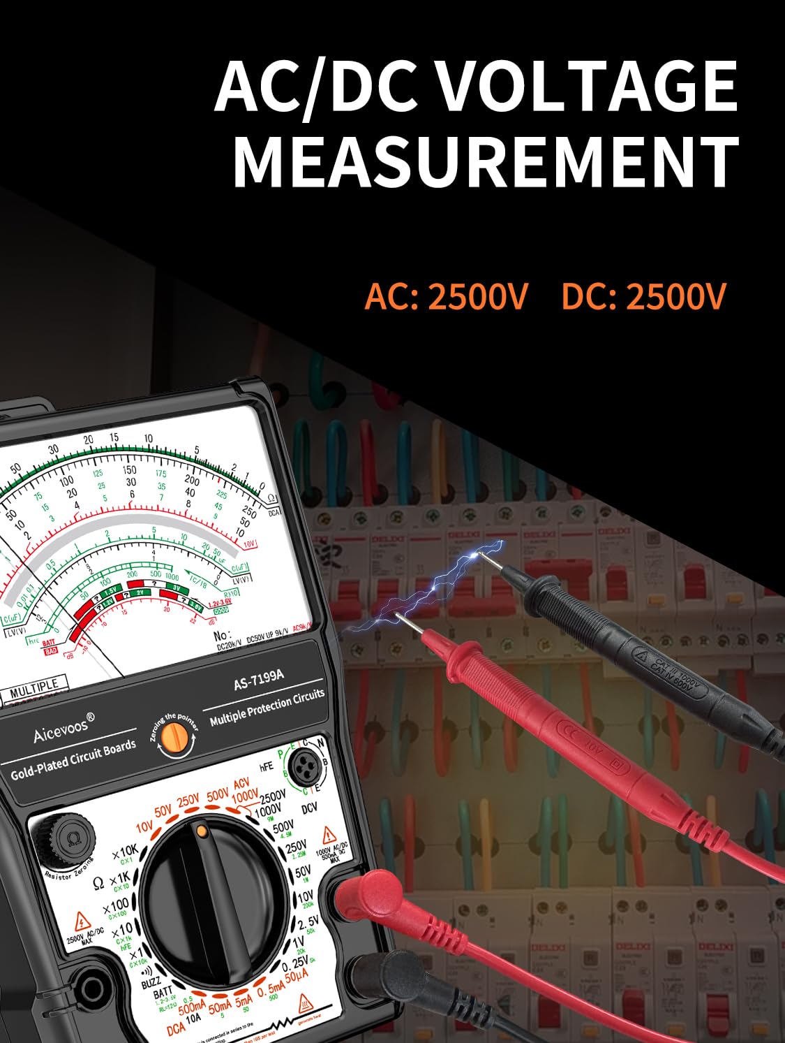
Figure 2: Measuring AC/DC Voltage. The multimeter can measure up to 2500V AC or DC.
5.2. DC Current Measurement
To measure DC current up to 10A:
- Set the function switch to the desired DCA range (e.g., 10A, 2.5A, 500mA, 50mA, 5mA, 0.5mA).
- Connect the multimeter in series with the circuit.
- Read the current value from the corresponding scale.
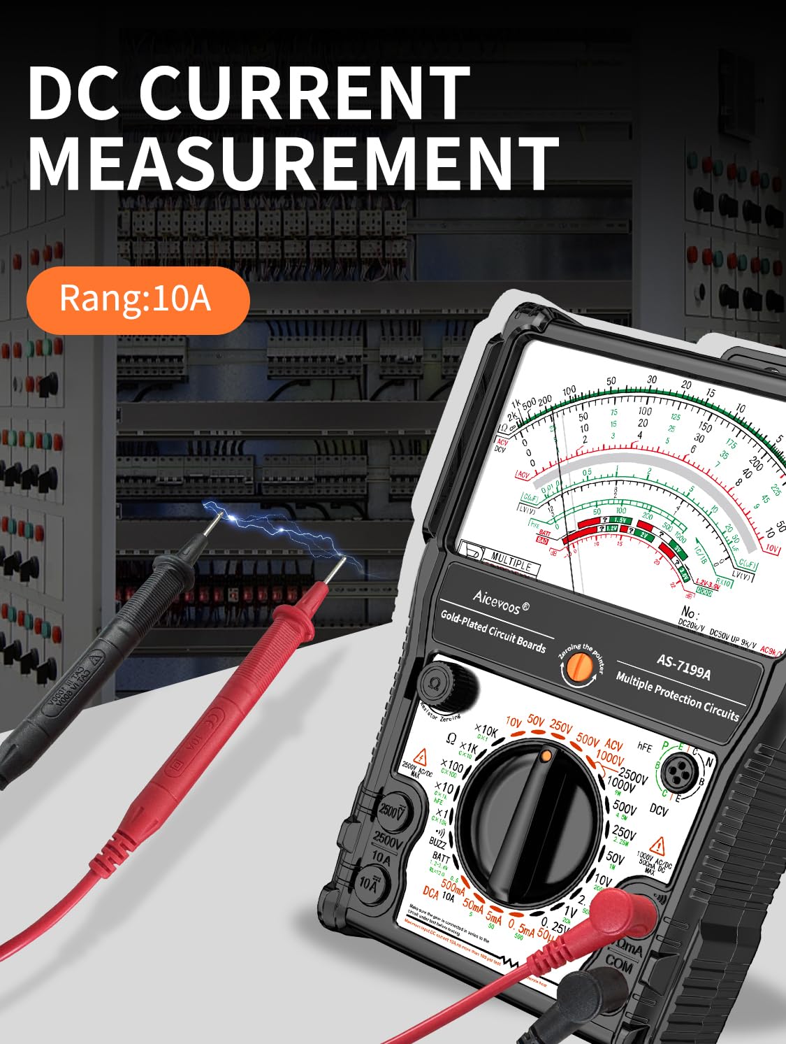
Figure 3: Measuring DC Current. The multimeter supports ranges up to 10A.
5.3. Resistance Measurement
To measure resistance up to Rx 100K:
- Set the function switch to the desired Ω (Ohms) range (e.g., Rx1, Rx10, Rx100, Rx1K, Rx10K, Rx100K).
- Before measuring, short the test leads together and adjust the "Ω ADJ" knob to zero the meter.
- Connect the test leads across the component to be measured.
- Read the resistance value from the Ohms scale.

Figure 4: Measuring Resistance. The multimeter can measure resistance up to 100K Ohms.
5.4. Continuity and Buzzer Measurement
To check for continuity with an audible buzzer:
- Set the function switch to the "BUZZ" or continuity range.
- Connect the test leads across the circuit or component.
- If continuity exists (low resistance), the buzzer will sound.

Figure 5: Performing Continuity and Buzzer Measurement.
5.5. Transistor hFE Measurement
To measure the DC current gain (hFE) of a transistor:
- Set the function switch to the "hFE" position.
- Identify the type of transistor (NPN or PNP) and its emitter, base, and collector leads.
- Insert the transistor leads into the corresponding sockets in the hFE test socket on the multimeter.
- Read the hFE value from the display.

Figure 6: Measuring Transistor hFE. The range for hFE is up to 1000.
5.6. Battery Test
To test the charge level of 1.5V or 9V batteries:
- Set the function switch to the "BATT" position (1.5V or 9V).
- Connect the red test lead to the positive (+) terminal of the battery and the black test lead to the negative (-) terminal.
- Read the battery condition from the meter scale.
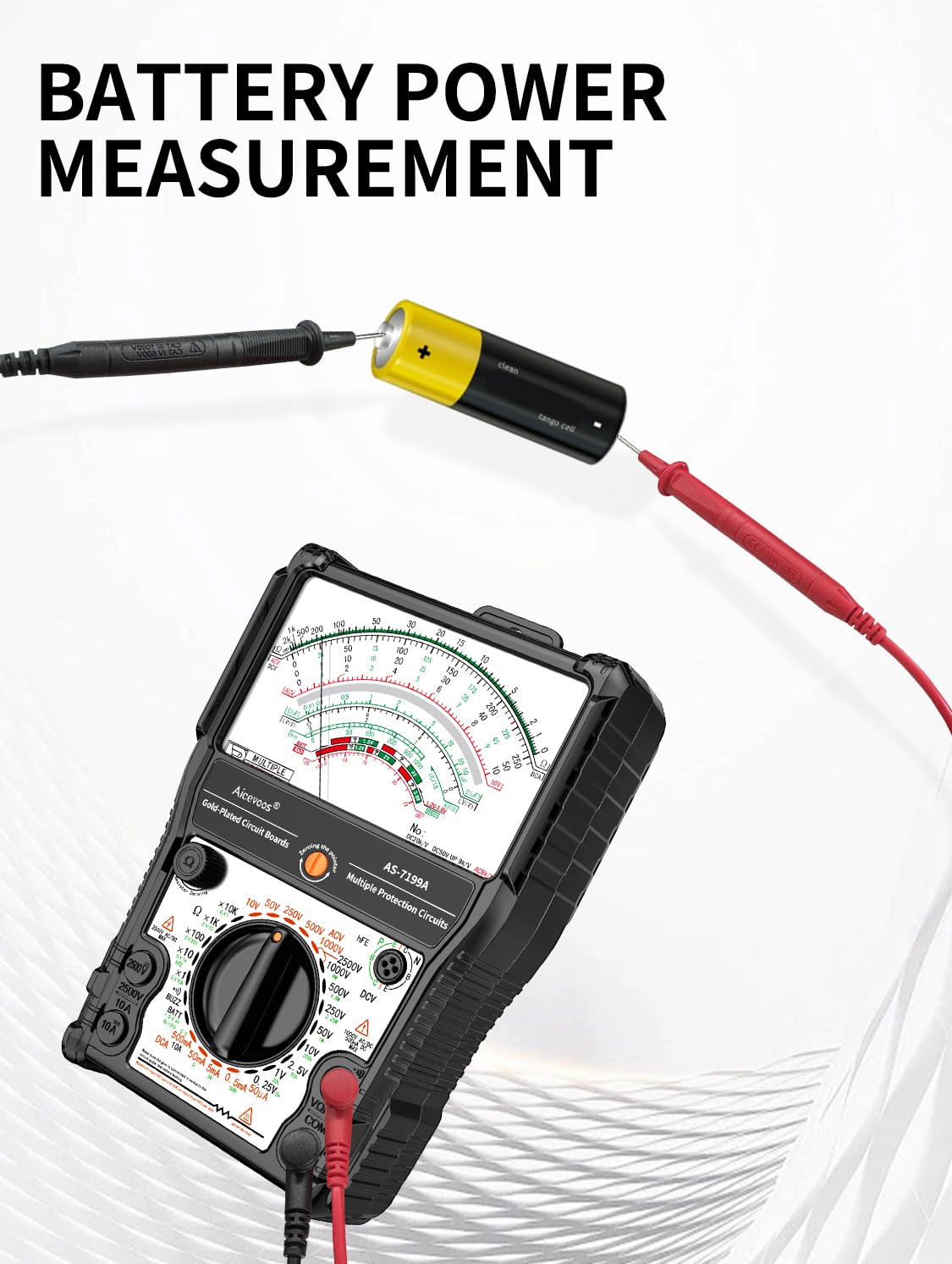
Figure 7: Performing a Battery Power Measurement.
5.7. Other Functions
The AS-7199A also includes functions for:
- Standard Resistance Box: For precise resistance values.
- LV Detection: Low Voltage detection.
- Regulator/LED Detection: For testing regulators and LEDs.
- Remote Control Detection: To check infrared remote control signals.
Refer to the specific markings on the multimeter dial for range selection and connection points for these functions.
6. Maintenance
6.1. Cleaning
Wipe the case with a damp cloth and mild detergent. Do not use abrasives or solvents.
6.2. Fuse Replacement
If the current measurement function stops working, the fuse may need replacement.
- Ensure the multimeter is disconnected from all circuits and turned off.
- Open the battery compartment cover.
- Locate the fuse(s) inside.
- Carefully remove the old fuse and replace it with a new fuse of the same type and rating (e.g., F 0.5A/250V for mA range, F 10A/250V for 10A range).
- Close the battery compartment cover.
6.3. Storage
When not in use for extended periods, remove the batteries to prevent leakage and store the multimeter in a cool, dry place.
7. Troubleshooting
| Problem | Possible Cause | Solution |
|---|---|---|
| No reading or erratic readings |
|
|
| Current measurement not working | Blown fuse | Replace fuse (refer to Section 6.2) |
| Ohms reading is inaccurate or won't zero |
|
|
8. Specifications
| Parameter | Value/Range |
|---|---|
| Model | AS-7199A |
| Brand | Aicevoos |
| AC Voltage | Up to 2500V |
| DC Voltage | Up to 2500V |
| DC Current | Up to 10A |
| Resistance | Up to Rx 100K |
| hFE (Transistor Gain) | Up to 1000 |
| Power Source | 2 x 1.5V Batteries |
| Functions | 11 (AC/DC Voltage, DC Current, DC Resistance, Standard Resistance Box, On/Off Beep, Transistor, LV Detection, Regulator/LED Detection, Battery Detection, Remote Control Detection) |
| Ranges | 24 |
9. Warranty and Support
For warranty information and technical support, please refer to the contact details provided with your purchase or visit the official Aicevoos website. Keep your purchase receipt as proof of purchase for warranty claims.