1. Introduction and Overview
The MYPIN Digital Weighing Controller LM8-RRD is a precision instrument designed for accurate weight control and measurement applications. It features a 4-digit LED display, 2 relay outputs, and is compatible with 1-4 load cells. This manual provides essential information for the proper installation, operation, and maintenance of your weighing controller.
This device is suitable for various industrial applications requiring precise weight control, auto accumulation, and batch control.
2. Product Features
- High-precision digital weighing controller.
- 4-digit LED display for clear readings.
- Supports input from 1 to 4 load cells (mV input).
- Equipped with 2 independent relay outputs for control applications.
- Designed for weight control, auto accumulation, and batch control.
- Compact and durable design for industrial environments.
3. Specifications
| Parameter | Specification |
|---|---|
| Model | LM8-RRD (4 Digits) |
| Display | LED Display |
| Power Supply | 220V/110V AC |
| Accuracy | 0.2%F.S ± 2dgt |
| Power Consumption | ≤5VA |
| Sampling Rate | ≤16 times/second |
| Input | mV (Load Cell), 1-4 pcs Load Cell |
| Output | 2 RELAY |
| Relay Contact | Open Contact 250V AC 3A or 30V DC 3A COS=1 |
| Auxiliary Power | DC 5V |
| Item Size | 95 x 85 x 46mm / 3.74 x 3.35 x 1.81in |
| Item Weight | 258g / 9.12oz |
| Material | Plastic + Metal |
4. Setup and Installation
Proper installation is crucial for the accurate and safe operation of the weighing controller.
4.1 Package Contents
- 1 x Weighing Controller (LM8-RRD)
- 2 x Mounting Brackets
- 1 x User Manual (English)
4.2 Mounting the Controller
The controller is designed for panel mounting. Use the provided brackets to secure the unit into a suitable cutout. Ensure adequate ventilation around the unit.

Figure 4.2.1: Front view of the MYPIN Digital Weighing Controller showing the included mounting brackets on either side, ready for panel installation.
4.3 Wiring Connections
Refer to the wiring diagram on the top of the unit and the terminal block labels for correct connections. Ensure all power is disconnected before making any wiring connections.

Figure 4.3.1: Top view of the MYPIN Digital Weighing Controller, clearly displaying the wiring diagram for power input, alarm outputs (AL1, AL2), common (COM), auxiliary power (EXC5V), signal ground (SG), and mV input from load cells.

Figure 4.3.2: Side view of the MYPIN Digital Weighing Controller, highlighting the screw terminal blocks for secure electrical connections. The terminals are numbered for easy identification during wiring.
Power Supply Connection:
- Connect the AC 220V/110V power supply to terminals 1 (L) and 2 (N).
- Ensure the correct voltage is applied as per the unit's specification.
Load Cell Connection:
- Connect the load cell excitation voltage (EXC5V) to terminal 9 (+).
- Connect the load cell signal ground (SG) to terminal 10 (-).
- Connect the load cell mV signal to terminals 11 (+) and 12 (-).
- The unit supports 1 to 4 load cells. Ensure proper parallel connection for multiple load cells.
Relay Output Connection:
- The controller has 2 relay outputs (AL1, AL2) and a common (COM) terminal.
- Connect external devices to be controlled by the relays using terminals 4 (AL1), 5 (AL2), and 7 (COM).
- Relay contacts are Open Contact, rated for 250V AC 3A or 30V DC 3A.
5. Operating Instructions
The MYPIN Digital Weighing Controller features a user-friendly interface with a main display and control buttons.
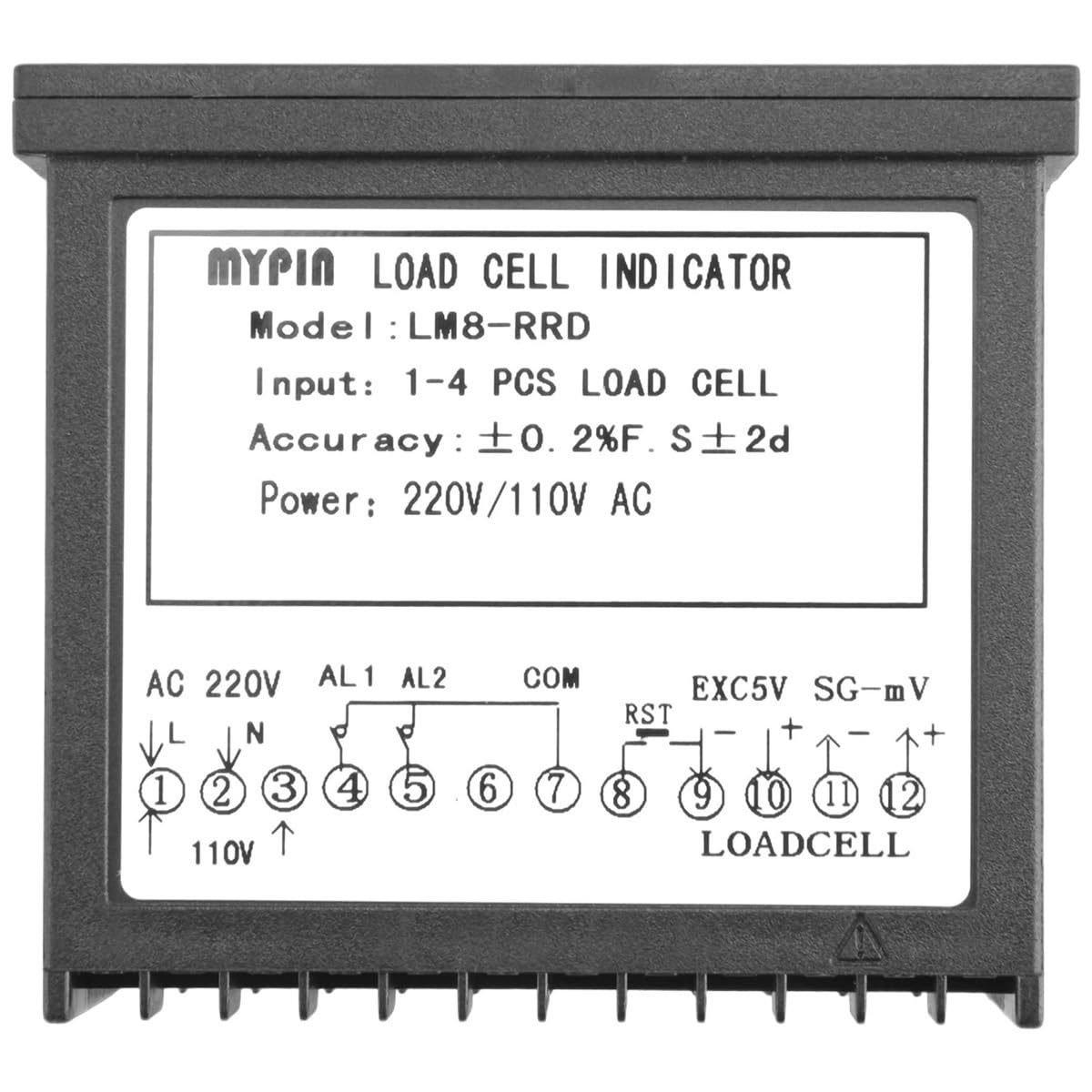
Figure 5.0.1: Front panel of the MYPIN Digital Weighing Controller, showing the main LED display and control buttons.

Figure 5.0.2: Angled view of the MYPIN Digital Weighing Controller's display, highlighting the PV (Process Value) and SV (Set Value) readouts, along with indicator lights for AL1, AL2, AL3, and units (g, T, Kg).
5.1 Display Overview
- PV (Process Value): The upper display shows the current measured weight or process value.
- SV (Set Value): The lower display shows the set point or target value.
- Indicators: Lights for AL1, AL2, AL3 (Alarm 1, 2, 3) and units (g, T, Kg) indicate status and measurement units.
5.2 Control Buttons
- SET: Used to enter parameter setting mode and confirm selections.
- </M (Shift/Mode): Used to shift digits during setting or change operating modes.
- ▲ (Up Arrow): Used to increase values or navigate up in menus.
- ▼ (Down Arrow): Used to decrease values or navigate down in menus.
5.3 Basic Operation
- Power On: After connecting power, the unit will perform a self-test and then display the current weight.
- Zeroing/Tare: Consult the detailed user manual (included in package) for specific instructions on zeroing the scale or performing tare operations, as this often involves a combination of button presses or a dedicated function.
- Setting Parameters:
- Press the SET button to enter the parameter setting mode.
- Use the ▲ and ▼ buttons to adjust the value of the currently selected parameter.
- Use the </M button to shift the cursor to different digits or move to the next parameter.
- Press SET again to confirm the setting and move to the next parameter, or to exit the setting mode.
- Calibration: Calibration procedures are critical for accurate weighing. Refer to the comprehensive user manual for detailed steps on how to calibrate the load cell input and ensure precise measurements. This typically involves applying known weights.
6. Maintenance
Regular maintenance ensures the longevity and reliable performance of your MYPIN Digital Weighing Controller.
- Cleaning: Use a soft, dry cloth to clean the display and casing. Do not use abrasive cleaners, solvents, or immerse the unit in water.
- Environmental Conditions: Ensure the operating environment is within the specified temperature and humidity ranges. Avoid excessive dust, moisture, and corrosive gases.
- Connection Check: Periodically inspect all wiring connections for tightness and signs of wear or corrosion.
- Calibration Check: For critical applications, perform periodic calibration checks to ensure continued accuracy.
7. Troubleshooting
This section addresses common issues you might encounter. For problems not listed here, please contact technical support.
| Problem | Possible Cause | Solution |
|---|---|---|
| No display/Unit not powering on | No power supply; Incorrect voltage; Loose wiring. | Check power connections and voltage. Ensure wiring is secure. |
| Inaccurate readings | Load cell issue; Calibration required; Environmental interference. | Verify load cell connections. Perform calibration. Check for vibrations or temperature fluctuations. |
| Relays not activating | Incorrect set points; Wiring error; Relay failure. | Check SV settings. Verify relay output wiring. Test relay functionality. |
| Display shows "OVER" or "----" | Overload condition; Load cell disconnected or faulty. | Reduce load. Check load cell wiring and integrity. |
8. Warranty and Support
For specific warranty terms and conditions, please refer to the warranty card included with your product or visit the official FCNGEVBH website.
If you require technical assistance, troubleshooting beyond this manual, or have questions regarding your MYPIN Digital Weighing Controller, please contact the manufacturer's customer support.
Manufacturer: FCNGEVBH
Model: LM8-RRD