1. Introduction
This manual provides comprehensive instructions for the installation, operation, maintenance, and troubleshooting of the XIYICONTROL SMC Valve Island Module, specifically the EX245-SDN1-X35 model. Please read this manual thoroughly before using the product to ensure safe and efficient operation.
The SMC Valve Island Module is designed for industrial automation applications, providing centralized control and connectivity for pneumatic valves. Its modular design allows for flexible configuration and integration into various control systems.
2. Safety Information
Always observe the following safety precautions to prevent injury and damage to the equipment:
- Ensure power is disconnected before performing any installation, maintenance, or wiring.
- Only qualified personnel should install, operate, and maintain this device.
- Do not exceed the specified voltage and current ratings.
- Protect the module from moisture, dust, and extreme temperatures.
- Verify all connections are secure before applying power.
3. Product Components and Overview
The SMC Valve Island Module EX245-SDN1-X35 is a compact and robust unit designed for reliable performance in industrial environments. It integrates multiple digital input/output ports for connecting various sensors and actuators.

Figure 3.1: Front view of the SMC Valve Island Module EX245-SDN1-X35. This image displays the module's front face, highlighting the multiple circular connectors labeled for digital inputs, indicating its primary function for signal integration.

Figure 3.2: Angled view of the SMC Valve Island Module EX245-SDN1-X35. This perspective provides a better understanding of the module's compact form factor and the arrangement of its various connectors, including the digital input ports.

Figure 3.3: Side view of the SMC Valve Island Module EX245-SDN1-X35, highlighting the bus connector interface. This view is crucial for understanding how the module connects to the main valve island system or other communication modules.
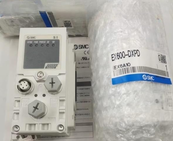
Figure 3.4: Close-up view of the bus connector on the SMC Valve Island Module EX245-SDN1-X35. This detailed image shows the pin configuration and design of the bus interface, essential for proper system integration.
Key Features:
- Modular design for flexible system expansion.
- Multiple digital input ports for sensor integration.
- Robust construction for industrial environments.
- Easy integration with existing SMC valve island systems.
4. Setup and Installation
4.1 Unpacking and Inspection
Upon receiving the module, carefully unpack it and inspect for any signs of damage during transit. Report any damage to the carrier immediately.
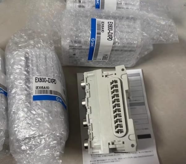
Figure 4.1: SMC Valve Island Module EX245-SDN1-X35 in its original packaging. This image shows the module securely wrapped in bubble wrap, indicating proper packaging for protection during shipping.

Figure 4.2: Close-up of the SMC Valve Island Module EX245-SDN1-X35 packaging, showing the product label. This view helps in verifying the model number and other product details upon receipt.
4.2 Mounting the Module
The EX245-SDN1-X35 module is designed for secure mounting within an industrial control panel or onto a compatible valve island manifold. Ensure adequate space for wiring and ventilation.
- Identify the appropriate mounting location, ensuring it is stable and free from excessive vibration.
- Align the module with the mounting points on the manifold or panel.
- Secure the module using appropriate fasteners (e.g., screws or clips) as per the manifold's design. Do not overtighten.
4.3 Electrical Connections
Refer to the wiring diagram provided with your complete valve island system for specific connection details. Ensure all power is off before making any electrical connections.
- Power Supply: Connect the module to a stable and regulated power supply within the specified voltage range.
- Digital Inputs: Connect sensors or input devices to the designated digital input ports. Pay attention to polarity and signal type (NPN/PNP).
- Bus Communication: Connect the module to the main communication bus (e.g., Ethernet/IP, Profibus, DeviceNet) of your control system using the appropriate bus connector.
5. Operating Instructions
5.1 Powering On
Once all connections are secure and verified, apply power to the valve island system. The module's status indicators should illuminate, indicating proper power and communication.
Figure 5.1: SMC Valve Island Module EX245-SDN1-X35 with visible status indicators. This image shows the module's display and LED indicators, which provide visual feedback on its operational status, power, and communication activity.
5.2 Configuration and Programming
The EX245-SDN1-X35 module is typically configured and programmed via the main control system (PLC or industrial PC) using the manufacturer's specific software tools. Refer to the software manual for detailed programming instructions.
- Assign I/O addresses for each digital input.
- Configure communication parameters to match the network settings.
- Test each input to ensure proper signal detection.
5.3 Normal Operation
During normal operation, the module will continuously monitor the status of connected digital inputs and transmit this data to the control system. The control system will then process this information to control associated pneumatic valves or other devices.
6. Maintenance
6.1 Routine Inspection
Perform regular visual inspections of the module and its connections:
- Check for loose connections or damaged wiring.
- Inspect for any signs of overheating, discoloration, or unusual odors.
- Ensure the module is free from dust, dirt, and moisture accumulation.
6.2 Cleaning
If cleaning is necessary, disconnect power to the module. Use a soft, dry cloth to wipe down the exterior. For stubborn dirt, a slightly damp cloth with mild detergent can be used, ensuring no liquid enters the module.
6.3 Firmware Updates
Periodically check the manufacturer's website for any available firmware updates. Follow the provided instructions carefully when performing updates to ensure compatibility and prevent data corruption.
7. Troubleshooting
This section provides solutions to common issues you may encounter with the EX245-SDN1-X35 module. For problems not listed here, contact technical support.
| Problem | Possible Cause | Solution |
|---|---|---|
| Module not powering on. | No power supply; incorrect wiring; faulty power supply. | Check power connections and voltage. Verify power supply functionality. |
| Communication error with PLC. | Incorrect bus wiring; wrong communication settings; faulty bus cable. | Verify bus cable integrity. Check communication settings in PLC and module. Ensure proper bus termination. |
| Digital input not responding. | Sensor not connected; faulty sensor; incorrect input wiring; incorrect I/O mapping. | Check sensor connection and functionality. Verify input wiring polarity. Confirm I/O mapping in PLC program. |
| Module overheating. | Insufficient ventilation; ambient temperature too high; internal fault. | Ensure proper airflow around the module. Reduce ambient temperature if possible. Disconnect power and contact support if problem persists. |
8. Specifications
The following table outlines the key technical specifications for the SMC Valve Island Module EX245-SDN1-X35:
| Parameter | Value |
|---|---|
| Model Number | EX245-SDN1-X35 |
| Brand | XIYICONTROL |
| Manufacturer | CCGK |
| Product Dimensions (L x W x H) | 0.1 x 0.1 x 0.1 inches |
| Country of Origin | China |
| ASIN | B0F4KMB7KL |
| UPC | 747515995239 |
| Date First Available | April 11, 2025 |
9. Warranty Information
This product is covered by a standard manufacturer's warranty. For specific warranty terms and conditions, please refer to the documentation provided with your purchase or contact the manufacturer directly. The warranty typically covers defects in materials and workmanship under normal use.
Note: Any unauthorized modifications, improper installation, or misuse of the product will void the warranty.
10. Technical Support and Contact
If you require further assistance or encounter issues not covered in this manual, please contact XIYICONTROL technical support.
- Manufacturer: CCGK
- Seller: CHENCHENGONGKONH (via Amazon)
- For support inquiries, please visit the seller's page on Amazon or refer to the contact information provided with your purchase.
When contacting support, please have your product model number (EX245-SDN1-X35) and ASIN (B0F4KMB7KL) ready for faster service.