1. Introduction
This manual provides essential information for the safe and efficient operation, installation, and maintenance of your DEWIN Single-Phase Frequency Inverter. Please read this manual thoroughly before using the product and retain it for future reference.
The DEWIN Single-Phase Frequency Inverter is designed to control the speed of single-phase motors, offering stable performance, intelligent protection, and efficient heat dissipation. It is suitable for a wide range of industrial applications.
2. Safety Information
WARNING: Read the user manual completely before operation. Risk of electrical shock. Wait 10 minutes after removing power before servicing to allow capacitors to discharge.
- Ensure all wiring is performed by a qualified electrician in accordance with local and national electrical codes.
- Always disconnect power before making any connections or performing maintenance.
- Do not operate the inverter with damaged cables or if the casing is open.
- Protect the unit from moisture, dust, and direct sunlight.
- Ensure proper grounding of the inverter and connected equipment.
- Do not touch internal components while the unit is powered or immediately after power disconnection.
3. Product Overview
The DEWIN Single-Phase Frequency Inverter (Model JLS-E-2S-2.2GB) is a robust device designed for precise motor speed control. It features a user-friendly control panel and a durable housing.
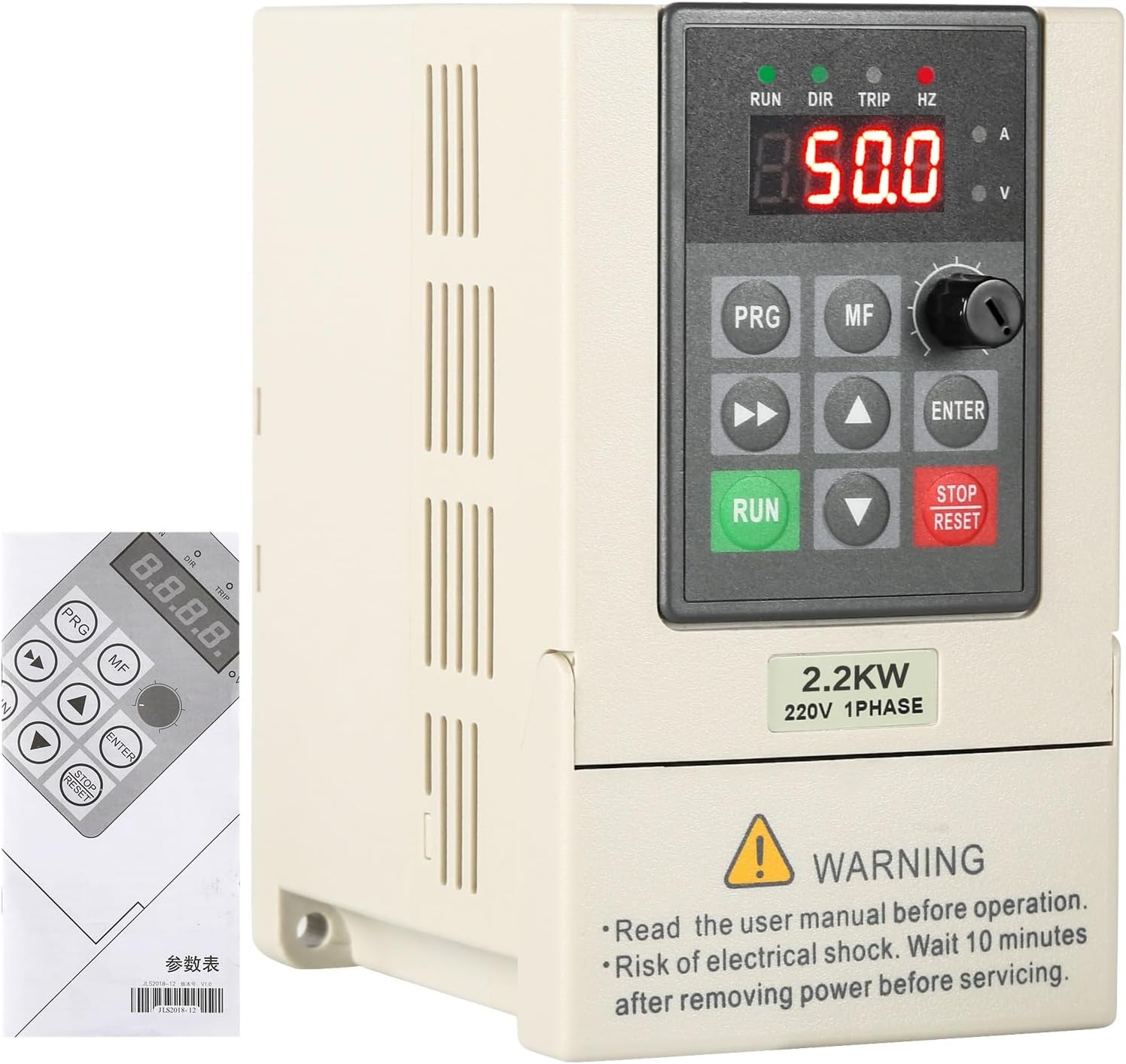
Figure 3.1: Front view of the DEWIN Single-Phase Frequency Inverter with its control panel and a portion of the instruction manual.
Key Features:
- Stable Performance: Utilizes a unique control method with a high double-layer configuration (power board + main board) for high power, torque, precision, and a wide speed control range.
- Intelligent Protection: Includes over-voltage, under-voltage, over-current, overload, over-temperature, power module protection, grounding protection, short-circuit protection, and stall protection for comprehensive energy safety.
- Efficient Heat Dissipation: Equipped with a powerful radiator and intelligent start/stop control to effectively reduce heat generated during operation.
- High Quality: Provides continuous and stable square wave output with a built-in AVR stabilizer. Adopts IPM and IGBT module design for improved efficiency, strong output, low heat generation, and automatic protection.

Figure 3.2: Visual representation of the inverter's benefits, including frequency control, energy saving, strong security, and engine protection.
Components:
The inverter consists of a main unit and a detachable control panel. The control panel allows for easy operation and parameter adjustment.

Figure 3.3: The control panel can be easily removed for flexible installation and wiring access.
The unit also features an integrated radiator for effective heat management.

Figure 3.4: The inverter is equipped with a radiator to ensure efficient heat dissipation and long-term stable functioning.
4. Specifications

Figure 4.1: Summary of product specifications.
| Parameter | Value |
|---|---|
| Material | Flame retardant ABS plastic |
| Color | White |
| Rated Input Voltage | Single-phase 220 V |
| Rated Output Voltage | Single-phase 220 V |
| Rated Power | 2.2 KW |
| Output Current | 10A |
| Factory Frequency | 50/60Hz |
| Output Frequency | 0~999 Hz |
| Installation Method | Wall-mounted, cabinet type |
| Dimensions (L*W*H) | 23 x 17 x 16 cm |
| Weight | 1.4 kg |
| DC Power Supply Nature | Voltage type |
| Control Mode | V/F closed loop |
| Output Voltage Adjustment Method | PAM control |
5. Setup and Wiring
Proper wiring is crucial for the safe and correct operation of the frequency inverter. Refer to the diagrams below for connection instructions.
Power and Motor Connections:
Connect the 220V single-phase power supply to the R and S terminals. Connect the single-phase motor to the U, V, and W terminals. Ensure the ground cable is properly connected to the ground terminal.
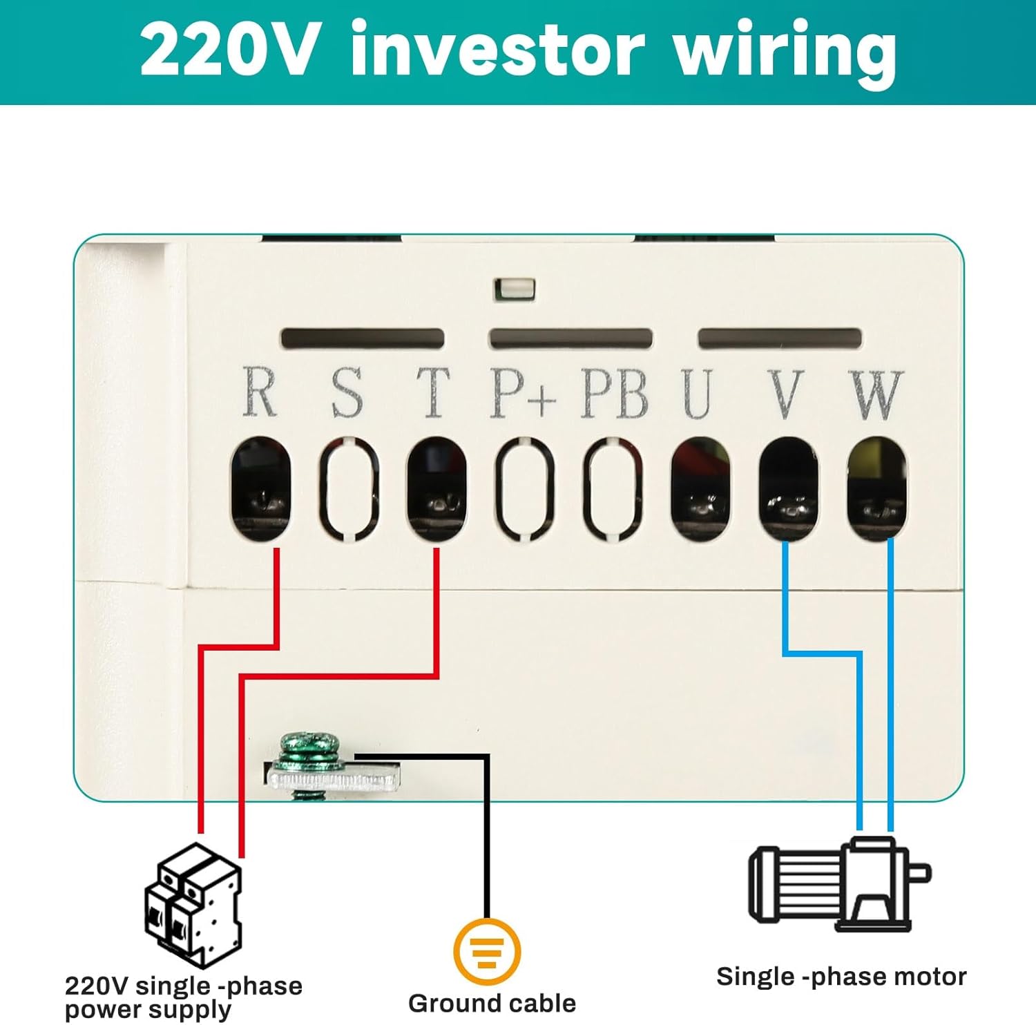
Figure 5.1: Basic 220V inverter wiring for single-phase input and motor output.
Control Terminal Wiring:
The inverter provides various control terminals for advanced functionalities such as external start/stop, frequency command input (analog voltage/current), and multi-function inputs. Consult the detailed wiring diagram for specific connections.

Figure 5.2: Detailed wiring instructions for control terminals, including frequency command, multi-function inputs, and output contacts.
- Power Input (R, S): Connect to 220V single-phase AC power.
- Motor Output (U, V, W): Connect to the single-phase motor.
- Ground (E): Connect to a reliable ground.
- Control Terminals (X1-X5, GND, AV1, AO, 485+, 485-): These terminals allow for external control signals, analog frequency input (0-10VDC or 4-20mA), and RS485 communication. Refer to the diagram for specific functions and jumper settings (J7, J8, J2, J5).
6. Operating Instructions
The control panel allows for direct operation and parameter setting. Familiarize yourself with the buttons and display before operation.
Control Panel Functions:
- Display: Shows current frequency (Hz), voltage (V), current (A), and other parameters.
- PRG (Program): Enters/exits parameter setting mode.
- MF (Multi-Function): Used for specific multi-function operations or menu navigation.
- Up/Down Arrows: Adjust values or navigate through menus.
- Left/Right Arrows: Shift cursor during parameter editing.
- ENTER: Confirms selection or parameter changes.
- RUN: Starts the motor.
- STOP/RESET: Stops the motor or resets errors.
- Rotary Knob: Adjusts frequency or other parameters quickly.
Basic Operation:
- Power On: Ensure all connections are secure and power on the inverter. The display will light up.
- Set Frequency: Use the rotary knob or arrow buttons to set the desired output frequency.
- Start Motor: Press the RUN button to start the motor.
- Stop Motor: Press the STOP/RESET button to stop the motor.
- Parameter Adjustment: Press PRG to enter parameter setting mode. Use arrow keys to navigate and ENTER to select and confirm changes. Refer to the full user manual for detailed parameter descriptions.
7. Maintenance
Regular maintenance ensures the longevity and optimal performance of your inverter.
- Cleaning: Keep the inverter clean and free from dust and debris. Use a soft, dry cloth for cleaning. Do not use liquid cleaners.
- Ventilation: Ensure that the ventilation openings are not obstructed to allow for proper heat dissipation.
- Connections: Periodically check all electrical connections for tightness and signs of wear or corrosion.
- Environment: Operate the inverter within its specified environmental conditions (temperature, humidity).
8. Troubleshooting
If you encounter issues with your DEWIN Frequency Inverter, refer to the following basic troubleshooting steps. For complex problems, contact technical support.
- No Power/Display: Check the main power supply and all power connections. Ensure the circuit breaker is not tripped.
- Motor Not Starting: Verify that the RUN command is active. Check motor wiring. Ensure frequency is set above 0 Hz. Check for error codes on the display.
- Overload/Overcurrent Error: Reduce the motor load. Check for mechanical issues with the motor or driven equipment. Verify motor parameters are correctly set in the inverter.
- Overvoltage/Undervoltage Error: Check the input power supply voltage. Ensure it is within the specified range (220V ±15%).
- Overheating Error: Ensure adequate ventilation around the inverter. Clean any dust from the radiator fins. Check ambient temperature.
9. Warranty and Support
For warranty information, technical support, or service inquiries, please contact your DEWIN product supplier or refer to the warranty card included with your purchase. Provide your product model number (JLS-E-2S-2.2GB) and serial number when contacting support.
You can also visit the official DEWIN store for more information: DEWIN Store


