1. Introduction
Thank you for choosing the STANLEY Iper Mig 130 Inverter Welder. This manual provides essential information for the safe and efficient operation, maintenance, and troubleshooting of your welding machine. Please read this manual thoroughly before operating the welder to ensure proper use and to prevent injury or damage.
1.1 Important Safety Information
Always observe the following safety precautions to minimize risks associated with welding:
- Read and understand all instructions and safety warnings in this manual before use.
- Wear appropriate personal protective equipment (PPE), including welding helmet, gloves, protective clothing, and safety shoes.
- Ensure adequate ventilation in the work area to disperse welding fumes.
- Never operate the welder in damp or wet conditions.
- Ensure the welder is properly grounded.
- Keep children and unauthorized personnel away from the welding area.
- Disconnect power before performing any maintenance or adjustments.
2. Product Overview and Components
The STANLEY Iper Mig 130 is a versatile inverter welder designed for MMA (Shielded Metal Arc Welding), TIG LIFT, and MIG (Gas Metal Arc Welding) processes. It features a robust metal body, an ergonomic handle, a soft-touch regulation knob, and a digital display for multi-process functions, ensuring durability and precise control.
2.1 Included Components
The following items are included with your STANLEY Iper Mig 130 Inverter Welder:
- STANLEY Iper Mig 130 Inverter Welder (130 Amp, 127V)
- Electrode Holder Cable
- Ground Clamp
- MIG Torch
- Shoulder Strap
- User Manual
2.2 Welder Features and Controls
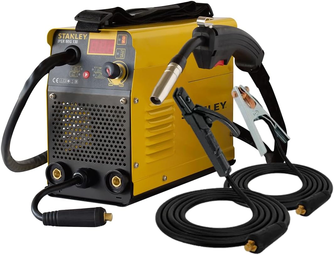
Figure 1: The STANLEY Iper Mig 130 Inverter Welder, including the main unit, MIG torch, electrode holder cable, and ground clamp cable.

Figure 2: Visual representation of the welder's dimensions. The official specifications are listed in Section 3.

Figure 3: The electrode holder cable and ground clamp cable, essential accessories for MMA welding.
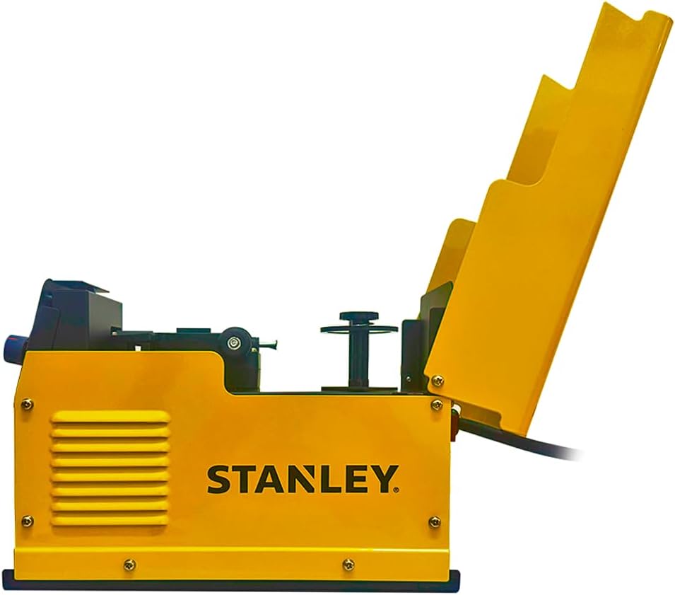
Figure 4: Internal view of the wire feed mechanism, accessible by opening the side panel, used for MIG welding.
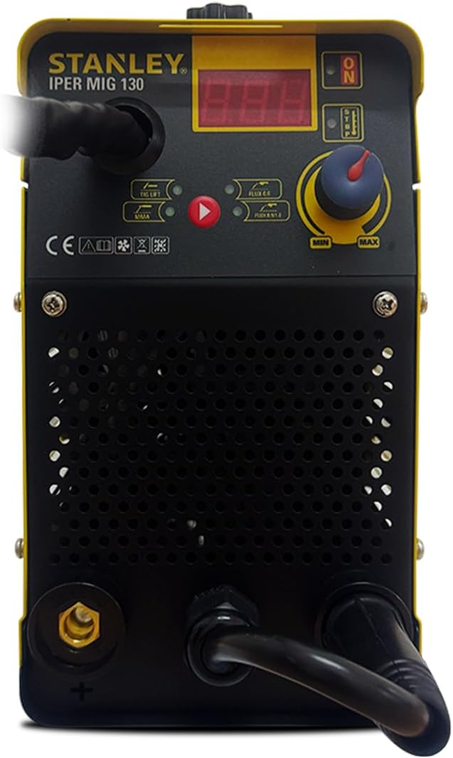
Figure 5: Close-up view of the welder's front panel, featuring the digital display, control knob, and mode selection indicators for MMA, TIG LIFT, and MIG processes.
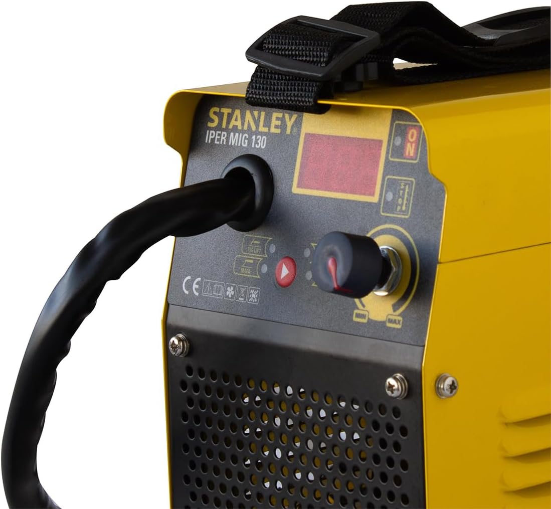
Figure 6: Detailed view of the soft-touch regulation knob and digital display, used for adjusting welding current and monitoring settings.
3. Technical Specifications
| Feature | Specification |
|---|---|
| Power | 130 AMP |
| Connectors | 3/8" |
| Voltage | 127V / 50-60Hz |
| Digital Display | Yes |
| Welding Processes | MMA / TIG LIFT / MIG |
| Weldable Materials | Stainless Steel / Cast Iron |
| Recommended MMA Electrodes | 6013 / 7018 |
| Intended Use | Industrial and general welding applications |
| MMA Specifications | |
| Absorbed Power (127V) | 3.7kVA / 2.7kW |
| Open Circuit Voltage (127V) | 59V |
| Welding Current (127V) | 10-110A |
| Duty Cycle EN 60974-1 (127V) | 20/100A |
| Duty Cycle (127V) | 100A@60% |
| Electrode Diameter Range (127V) | 1.6-2.5mm |
| TIG LIFT Specifications | |
| Absorbed Power (127V) | 2.2kVA / 1.7kW |
| Open Circuit Voltage (127V) | 15.5-20V |
| Welding Current (127V) | 10-100A |
| Duty Cycle EN 60974-1 (127V) | 20/100A |
| Duty Cycle (127V) | 100A@60% |
| Electrode Diameter Range (127V) | 1.6-2.4mm |
| MIG Specifications | |
| Absorbed Power (127V) | 3kVA / 2.2kW |
| Open Circuit Voltage (127V) | 15.5-20V |
| Welding Current (127V) | 30-100A |
| Duty Cycle EN 60974-1 (127V) | 20/100A |
| Duty Cycle (127V) | 100A@60% |
| Welding Wire Diameter | 0.8 / 0.9 / 1.0 mm |
| Physical Specifications | |
| Dimensions (L x W x H) | 49.5 x 26 x 37.5 cm |
| Weight | 12.9 Kg |
4. Setup
4.1 Unpacking
- Carefully remove the welder and all accessories from the packaging.
- Inspect all components for any signs of damage during transit. If any damage is found, do not operate the machine and contact customer support.
- Verify that all included components listed in Section 2.1 are present.
4.2 Power Connection
Connect the welder to a dedicated 127V / 50-60Hz power outlet. Ensure the power source can handle the absorbed power requirements of the welder (refer to Section 3). Use a properly grounded outlet and avoid using extension cords if possible. If an extension cord is necessary, ensure it is rated for the welder's power requirements and is in good condition.
4.3 Connecting Accessories
- Ground Clamp: Connect the ground clamp cable to the appropriate terminal on the welder (usually marked with a ground symbol or '-'). Securely attach the ground clamp to the workpiece or welding table, ensuring good electrical contact.
- Electrode Holder (for MMA): Connect the electrode holder cable to the positive terminal on the welder (usually marked with '+'). Insert the welding electrode into the holder.
- MIG Torch (for MIG): Connect the MIG torch to the designated connector on the front panel. Ensure the wire feed mechanism is properly loaded with welding wire (refer to MIG operating instructions).
- TIG Torch (for TIG LIFT): If using TIG LIFT, connect a TIG torch (not included) to the appropriate terminal.
5. Operating Instructions
5.1 General Operation
- After connecting all accessories and power, turn on the welder using the main power switch.
- The digital display will illuminate. Use the mode selection buttons or switch to choose your desired welding process (MMA, TIG LIFT, or MIG).
- Adjust the welding current using the soft-touch regulation knob. The digital display will show the current setting.
- Always perform a test weld on scrap material to verify settings before working on your main project.
5.2 MMA (Shielded Metal Arc Welding) Mode
MMA welding uses a consumable electrode coated with flux. This process is suitable for various materials and outdoor conditions.
- Select MMA mode on the welder.
- Insert the appropriate electrode (e.g., 6013, 7018) into the electrode holder.
- Set the welding current according to the electrode manufacturer's recommendations and material thickness.
- Strike an arc by lightly touching the electrode to the workpiece and quickly lifting it slightly to establish the arc.
- Maintain a consistent arc length and travel speed for a quality weld.
5.3 TIG LIFT Mode
TIG LIFT welding provides a cleaner weld with precise control, ideal for thinner materials and stainless steel. A TIG torch (not included) and shielding gas are required for this process.
- Select TIG LIFT mode on the welder.
- Connect your TIG torch and shielding gas supply.
- Install a tungsten electrode of the correct diameter (1.6-2.4mm) in the torch.
- Set the welding current.
- Initiate the arc by gently touching the tungsten electrode to the workpiece and lifting it slightly. The arc will start without high-frequency interference.
- Maintain a short arc length and feed filler rod manually if required.
5.4 MIG (Gas Metal Arc Welding) Mode
MIG welding uses a continuously fed wire electrode and shielding gas (or flux-cored wire without gas) for fast and efficient welding.
- Select MIG mode on the welder.
- Loading Welding Wire: Open the side panel to access the wire feed mechanism (refer to Figure 4). Install the welding wire spool, ensuring the wire feeds smoothly through the drive rollers and into the MIG torch liner. Close the panel.
- Connect your shielding gas supply (if using solid wire) or ensure you are using flux-cored wire.
- Set the welding current and wire feed speed. These settings are often interdependent; consult a welding chart for guidance.
- Depress the trigger on the MIG torch to start the wire feed and initiate the arc.
- Maintain a consistent gun angle and travel speed.
6. Maintenance
Regular maintenance ensures the longevity and optimal performance of your welder. Always disconnect the welder from the power supply before performing any maintenance.
- Cleaning: Periodically clean the welder's exterior with a dry, soft cloth. Use compressed air to blow out dust and debris from the cooling vents.
- Cable Inspection: Regularly inspect all cables (power, electrode, ground, MIG torch) for cuts, fraying, or damaged insulation. Replace damaged cables immediately.
- MIG Torch Maintenance: Clean the MIG torch nozzle and contact tip regularly. Replace worn contact tips to ensure good electrical contact and wire feed.
- Storage: Store the welder in a clean, dry environment, away from moisture and extreme temperatures.
7. Troubleshooting
This section addresses common issues you might encounter with your welder. For problems not listed here, contact customer support.
| Problem | Possible Cause | Solution |
|---|---|---|
| Welder does not power on | No power supply; Faulty power cable; Main switch off | Check power outlet and circuit breaker; Inspect power cable; Ensure main switch is ON. |
| No arc (MMA/TIG) | Poor ground connection; Incorrect current setting; Wet electrode; Faulty cable | Ensure ground clamp has good contact; Adjust current; Use dry electrodes; Check cables for damage. |
| Poor weld quality | Incorrect current/voltage; Improper travel speed/arc length; Contaminated workpiece | Adjust settings; Practice technique; Clean workpiece thoroughly. |
| Overheating indicator active | Exceeded duty cycle; Blocked ventilation; High ambient temperature | Allow welder to cool down; Clear ventilation openings; Work in a cooler environment. |
| Wire feed issues (MIG) | Kinked wire; Worn contact tip; Incorrect drive roller tension; Blocked liner | Straighten wire; Replace contact tip; Adjust drive roller tension; Clean or replace liner. |
8. Warranty and Support
Your STANLEY Iper Mig 130 Inverter Welder is manufactured to high-quality standards and comes with a manufacturer's warranty. Please refer to the warranty card included with your product for specific terms and conditions.
For technical assistance, spare parts, or any other inquiries, please visit the official STANLEY website or contact their customer support. You can find more information and products from STANLEY by visiting their official store:


