1. Introduction
This manual provides detailed instructions for the installation, configuration, operation, and maintenance of your Generic X99H M-ATX Motherboard. Please read this guide thoroughly before proceeding with any installation or operation to ensure proper functionality and to prevent damage to the components.
2. Product Overview
The Generic X99H is an M-ATX form factor motherboard designed for high-performance computing, supporting LGA 2011-3 CPUs and DDR4 memory. It features multiple expansion slots and connectivity options for a versatile system build.
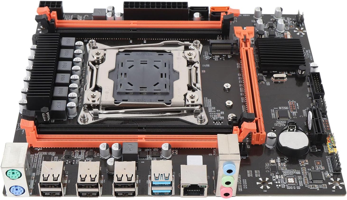
Figure 2.1: Top-down view of the Generic X99H M-ATX Motherboard, showcasing the CPU socket, RAM slots, and various connectors.

Figure 2.2: Angled view of the motherboard, highlighting the CPU socket, four DDR4 DIMM slots, and PCIe expansion slots.
3. Installation Guide
Follow these steps carefully to install your motherboard and its components.
3.1. CPU Installation
- Prepare the Socket: Gently lift the CPU socket retention arm on the LGA 2011-3 socket.
- Align the CPU: Carefully align your LGA 2011-3 CPU with the socket. Ensure the triangular mark on the CPU matches the mark on the socket. Do not force the CPU into the socket.
- Secure the CPU: Lower the CPU into the socket. Once seated, close the retention arm to secure the CPU in place.
- Apply Thermal Paste: Apply a small amount of thermal paste to the center of the CPU's integrated heat spreader (IHS).
- Install CPU Cooler: Mount your compatible CPU cooler according to its manufacturer's instructions.
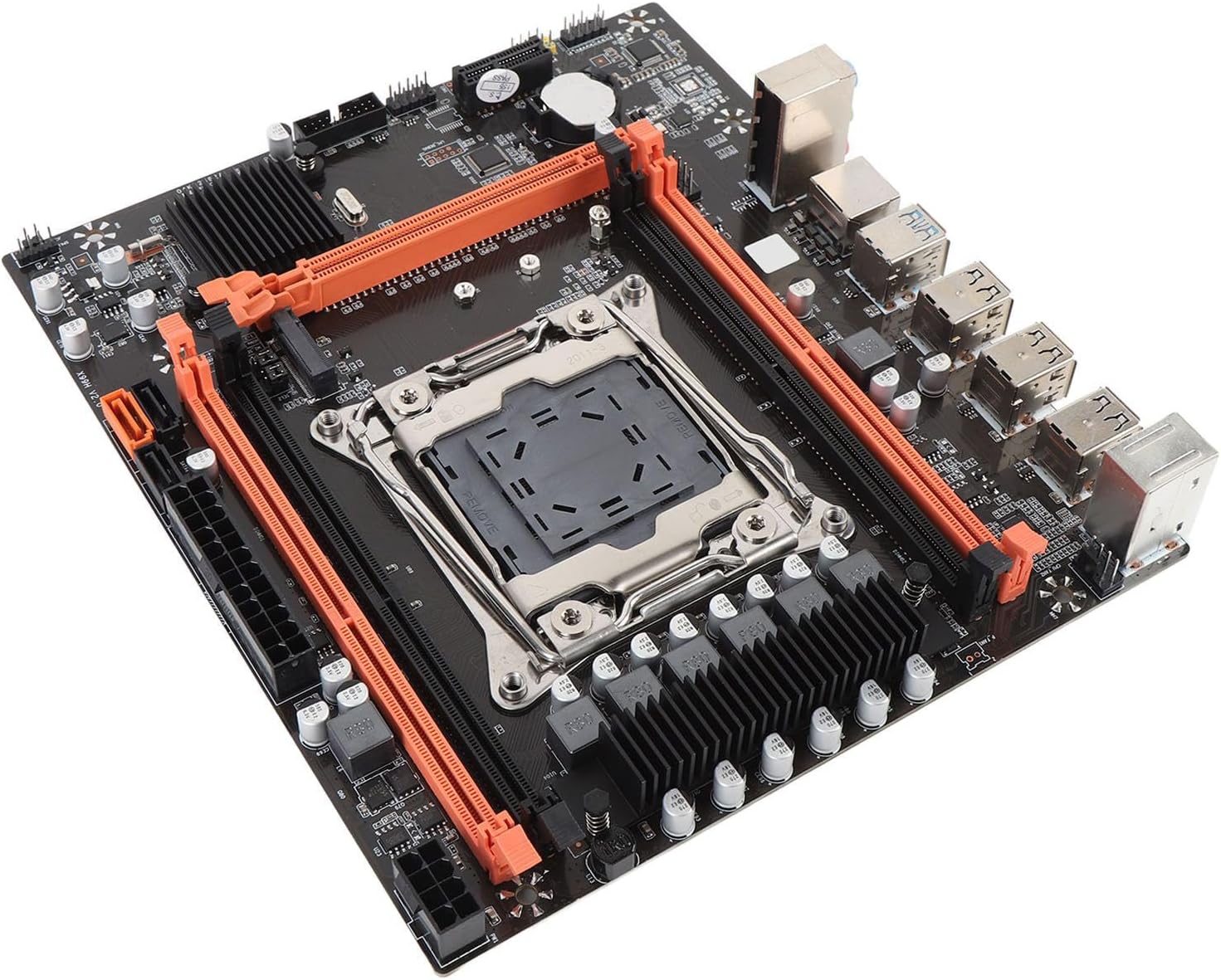
Figure 3.1: Close-up of the LGA 2011-3 CPU socket and adjacent DDR4 memory slots.
3.2. Memory (RAM) Installation
The X99H motherboard supports four DDR4 DIMM slots, with a maximum capacity of 128GB (32GB per slot). Supported memory speeds include 2666MHz, 2400MHz, and 2133MHz.
- Open Retention Clips: Open the white retention clips at both ends of the DIMM slot.
- Align Memory Module: Align the notch on the DDR4 memory module with the key in the DIMM slot.
- Insert Memory: Press down firmly on both ends of the memory module until the retention clips snap into place.
3.3. Storage Device Installation
The motherboard provides SATA 2.0, SATA 3.0, and M.2 slots for storage.
3.3.1. SATA Drives
- Connect SATA Data Cable: Connect one end of the SATA data cable to a SATA port on the motherboard (2 x SATA 2.0, 1 x SATA 3.0) and the other end to your SATA hard drive or SSD.
- Connect SATA Power Cable: Connect a SATA power cable from your power supply unit (PSU) to the SATA hard drive or SSD.
3.3.2. M.2 SSD
The motherboard features one NVME M.2 interface, supporting both NGFF and NVME protocols. A jumper switch may be present to select the mode.
- Locate M.2 Slot: Identify the M.2 slot on the motherboard.
- Insert M.2 SSD: Gently insert the M.2 SSD into the slot at a 30-degree angle.
- Secure M.2 SSD: Push the SSD down and secure it with the provided screw.

Figure 3.2: Close-up view of the M.2 slot, located near the chipset heatsink, for NVME or NGFF SSD installation.
3.4. Expansion Card Installation
The motherboard includes one PCIE x16 graphics card slot and one PCIE x1 slot.
- Locate PCIe Slot: Identify the appropriate PCIe slot for your expansion card (e.g., graphics card in the PCIE x16 slot).
- Insert Card: Align the card with the slot and press down firmly until it is fully seated.
- Secure Card: Secure the card to the chassis with a screw.
3.5. Power Supply Connection
Connect the power cables from your Power Supply Unit (PSU) to the motherboard.
- 24-pin ATX Power: Connect the main 24-pin ATX power connector from the PSU to the corresponding socket on the motherboard.
- 8-pin CPU Power: Connect the 8-pin CPU power connector (EPS12V) from the PSU to the socket near the CPU.

Figure 3.3: Close-up of the 24-pin ATX power connector, 8-pin CPU power connector, and SATA ports.
3.6. Front Panel & I/O Connections
Connect your case's front panel connectors and external peripherals to the motherboard's I/O ports.
- Front Panel Headers: Connect the power switch, reset switch, HDD LED, and power LED connectors from your case to the front panel header pins. Refer to the motherboard's silkscreen for correct pin assignments.
- USB Headers: Connect your case's front USB 2.0 and USB 3.0 ports to the corresponding USB headers on the motherboard (1 set USB3.0 pins, 1 set USB2.0 pins).
- Audio Header: Connect the front panel audio cable to the audio header.
- Rear I/O Ports: Connect peripherals such as keyboard (PS/2), mouse (PS/2), monitor (VGA, HD Multimedia), network cable (RJ45), and USB devices (6 x USB 2.0, 2 x USB 3.0) to the rear I/O panel.

Figure 3.4: Detailed view of the rear I/O panel, showing PS/2 ports, USB 2.0, USB 3.0, RJ45 LAN, and audio jacks.

Figure 3.5: The motherboard packaged with its I/O shield and a connecting cable, ready for installation.
4. Operating Instructions
4.1. Initial Boot-up
After completing all hardware installations, connect your monitor, keyboard, and mouse. Power on your system. The system should display the BIOS/UEFI splash screen.
4.2. BIOS/UEFI Setup
To enter the BIOS/UEFI setup utility, press the designated key (usually DEL or F2) during the initial boot sequence. In the BIOS/UEFI, you can configure boot order, system time, CPU settings, memory timings, and other hardware parameters.
4.3. Driver Installation
After installing your operating system, install the necessary drivers for the motherboard's components (chipset, LAN, audio, etc.). These drivers are typically provided on a CD/DVD included with the motherboard or can be downloaded from the manufacturer's website.
5. Maintenance
5.1. Cleaning
Regularly clean your computer's interior to prevent dust buildup, which can lead to overheating and component failure. Use compressed air to remove dust from heatsinks, fans, and other components. Ensure the system is powered off and unplugged before cleaning.
5.2. BIOS/Firmware Updates
Periodically check the manufacturer's website for updated BIOS/firmware versions. BIOS updates can improve system stability, add support for new hardware, or fix bugs. Follow the manufacturer's instructions carefully when performing a BIOS update to avoid system damage.
6. Troubleshooting
This section addresses common issues you might encounter.
6.1. No Power/No Boot
- Verify all power cables (24-pin ATX, 8-pin CPU) are securely connected to the motherboard and PSU.
- Ensure the PSU is switched on and connected to a working power outlet.
- Check front panel power switch connection to the motherboard.
- Test the PSU with another system or a PSU tester if available.
6.2. No Display
- Ensure the monitor is connected to the correct graphics output (either integrated or discrete graphics card).
- Reseat the graphics card and ensure its power connectors are attached (if applicable).
- Try a different monitor or display cable.
- If using integrated graphics, ensure your CPU supports it.
6.3. Memory Issues
- Ensure all RAM modules are fully seated in their slots.
- Try booting with only one RAM module installed, testing each module individually.
- Verify RAM compatibility with the motherboard and CPU.
6.4. Storage Detection Problems
- Check SATA data and power cable connections for all drives.
- Ensure M.2 SSD is properly seated and secured.
- Verify SATA mode (AHCI/RAID) settings in BIOS/UEFI.
- Check if the M.2 slot jumper switch is set correctly for NVME or NGFF.
7. Specifications
| Feature | Specification |
|---|---|
| Motherboard Structure | M-ATX |
| Chipset | X99H |
| CPU Socket | LGA 2011-3 |
| Supported CPU Types | E5 V3 V4, i7 58xx, 68xx series |
| Memory Slots | 4 x DDR4 DIMM |
| Max Memory Capacity | 128GB |
| Memory Types | DDR4 2666/2400/2133MHz |
| SATA Ports | 2 x SATA 2.0, 1 x SATA 3.0 |
| M.2 Slot | 1 x NVME M.2 Interface (supports NGFF/NVME with jumper switch) |
| PCIe Expansion Slots | 1 x PCIE x16, 1 x PCIE x1 |
| USB Interface (Rear I/O) | 6 x USB 2.0, 2 x USB 3.0 |
| USB Headers (Internal) | 1 set USB3.0 pins, 1 set USB2.0 pins |
| Video Output | VGA, HD Multimedia |
| Network | Onboard RJ45 Network Interface |
| PS/2 Interface | 1 x PS/2 Keyboard Mouse Universal Interface |
| Power Connectors | 1 x 24-pin ATX, 1 x 8-pin CPU |
| Built-in Battery | CR2032x1 240mah |
| Dimensions | 10.24 x 7.87 x 1.97 inches |
| Item Weight | 1.44 pounds |
| Model Number | Generick29mh7isay |
8. Warranty Information
Please refer to the specific warranty terms provided by your retailer or the manufacturer at the time of purchase. Typically, motherboards come with a limited warranty covering manufacturing defects. Keep your proof of purchase for warranty claims.
9. Support
For technical assistance, troubleshooting beyond this manual, or warranty inquiries, please contact the seller or manufacturer directly. Their contact information can usually be found on the product packaging or their official website.