1. Introduction
This manual provides detailed instructions for the installation, operation, and maintenance of the JIANGFAN 48V/60V/72V 50A 2000W Brushless Motor Sine Wave Electric Vehicle Controller. Please read this manual thoroughly before installation and use to ensure proper function and safety. This controller is designed for electric vehicles requiring a 48V, 60V, or 72V power supply and supports motors up to 2000W.
2. Safety Information
- Always disconnect power before performing any installation, maintenance, or troubleshooting.
- Ensure all connections are secure and properly insulated to prevent short circuits.
- Verify that the controller's voltage and power ratings match your motor and battery specifications. Using an incompatible controller may damage the motor or controller.
- Avoid exposing the controller to water, excessive moisture, or extreme temperatures.
- Installation should be performed by individuals with knowledge of electrical systems.
- Do not attempt to open or modify the controller casing, as this will void the warranty and may lead to electric shock.
3. Product Overview
The JIANGFAN Brushless Motor Sine Wave Electric Vehicle Controller is designed to provide efficient and smooth power delivery to your electric vehicle's motor. It features a robust design and supports multiple voltage inputs.
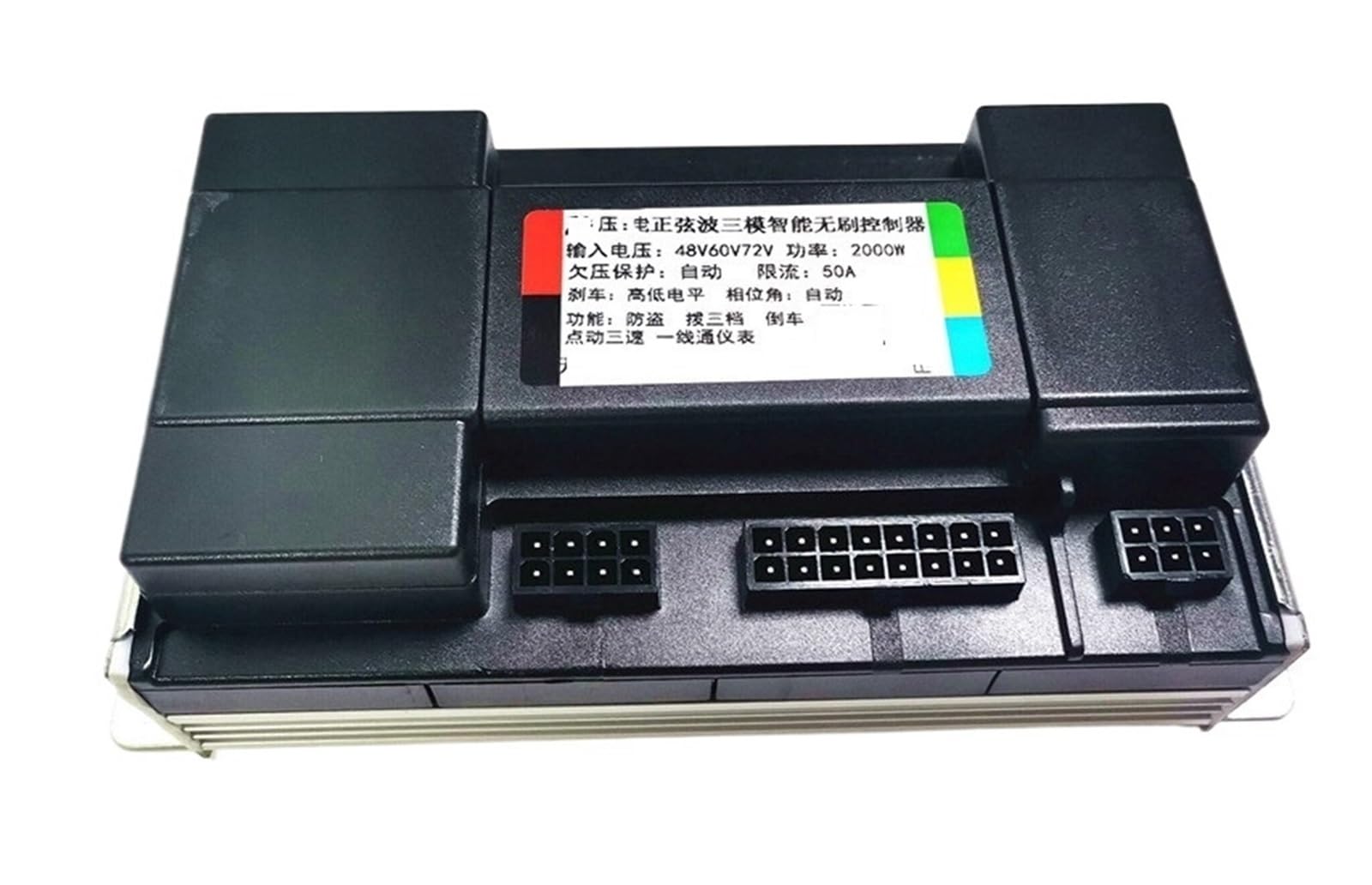
Figure 3.1: The JIANGFAN Brushless Motor Sine Wave Electric Vehicle Controller unit. This image shows the main controller unit with its heat sink fins and mounting brackets, indicating a durable and efficient design for power management.

Figure 3.2: The complete wiring harness for the controller. This image displays the various color-coded wires and connectors, essential for connecting the controller to the motor, battery, throttle, and other vehicle components.
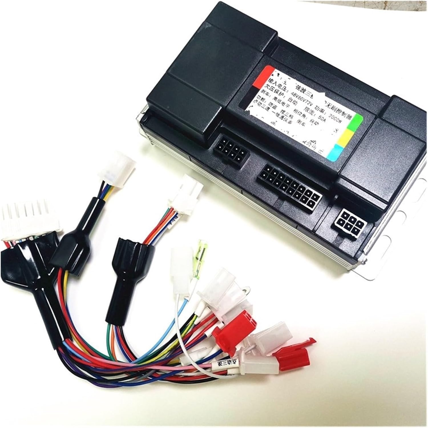
Figure 3.3: The JIANGFAN controller shown alongside its wiring harness. This view provides a perspective of the controller's size relative to its connections and illustrates how the harness integrates with the main unit.
4. Specifications
| Feature | Specification |
|---|---|
| Brand | JIANGFAN |
| Operating Voltage Range | 36V / 48V / 60V / 72V |
| Rated Power Range | 1200W - 1500W - 2000W |
| Current | 35A / 50A |
| Lithium Battery Undervoltage Protection | 30V / 40V / 50V / 60V |
| Peak Power | 2000W (working better at 1500W) |
| Motor Type | DC Motor (Brushless) |
| Item Weight | 50 Grams |
| Color | One Color |
5. Setup and Installation
Careful wiring is essential for the correct operation and safety of your electric vehicle. Refer to the wiring diagram below and the descriptions for each connection.

Figure 5.1: Detailed wiring diagram for the JIANGFAN controller. This diagram illustrates the various connection points and their functions, crucial for proper installation.
Wiring Connections:
- Red Fine Wire (Electric Door Lock): Connects to the electric door lock for power control.
- Positive Electrode (+): Main positive power input from the battery.
- Negative Electrode (-): Main negative power input from the battery.
- Phase Line of Motor: Connects to the motor's phase lines. Ensure correct phase matching.
- Handle (Speed Control Knob): Connects to the throttle or speed control handle.
- High Potential Braking: Connects to the high potential brake signal.
- Speedometer Yiyitong: Connects to the speedometer for speed display.
- Retrograde (Reverse): Connects to the reverse function switch.
- Anti-Theft Signal Line: Connects to the anti-theft system's signal output.
- Motor Hall: Connects to the motor's Hall sensors for position feedback.
- Anti-Theft Power Supply: Provides power to the anti-theft system.
- Three Speeds (Shift Three Speeds): Connects to the three-speed switch for speed mode selection.
- Inching Three Speed: Connects to the inching (low speed) switch.
- Self Study Line (Intelligent Self Identification): Used for motor identification and learning.
Self-Study Function (Intelligent Self Identification):
- Connect the motor, power supply, and other essential wires.
- Connect the two "Self Study Line" wires (usually white or green, as shown in the diagram).
- The motor will start rotating automatically. If the motor rotates in the correct direction, disconnect the self-study wires after 2-3 seconds. The identification is complete.
- If the motor rotates in the reverse direction, disconnect the self-study wires, then reconnect them. The motor will reverse direction. Disconnect the self-study wires after 2-3 seconds once the correct direction is achieved.
- This process allows the controller to learn the motor's parameters and phase sequence.
6. Operating Instructions
Once the controller is correctly installed and the self-study function is completed, the electric vehicle is ready for operation.
- Power On: Turn the electric door lock to the ON position. The controller will initialize.
- Speed Control: Use the throttle (speed control knob) to adjust the motor speed.
- Three-Speed Function: If connected, use the three-speed switch to select between different speed modes (e.g., low, medium, high).
- Inching Function: If connected, the inching switch provides a very low-speed movement for precise control.
- Braking: Apply the brakes. The high potential braking signal will cut off motor power for safety.
- Reverse: If a reverse switch is installed, activate it to engage the retrograde function.
7. Maintenance
To ensure the longevity and optimal performance of your controller, follow these maintenance guidelines:
- Keep the controller clean and free from dust and debris.
- Regularly inspect all wiring connections for looseness or damage. Tighten any loose connections.
- Ensure the controller is mounted in a location with adequate ventilation to prevent overheating.
- Avoid exposing the controller to harsh chemicals or solvents.
- If the controller shows signs of damage or malfunction, discontinue use and consult a qualified technician.
8. Troubleshooting
This section addresses common issues you might encounter with the controller.
| Problem | Possible Cause | Solution |
|---|---|---|
| Motor does not run | No power to controller; Loose connections; Faulty throttle; Motor or Hall sensor issue. | Check battery connection and voltage; Inspect all wiring; Test throttle functionality; Check motor and Hall sensor wires. |
| Motor runs in reverse after self-study | Self-study wires disconnected too early or reconnected incorrectly. | Repeat the self-study procedure, ensuring to disconnect and reconnect the self-study wires if the direction is incorrect, then disconnect permanently after correct rotation. |
| Intermittent power or erratic behavior | Loose wiring; Poor contact in connectors; Overheating. | Check all connections for tightness; Ensure proper ventilation for the controller; Inspect for any damaged wires. |
| Controller gets excessively hot | Overload; Insufficient ventilation; Short circuit. | Reduce load on the motor; Ensure controller is in a well-ventilated area; Check for short circuits in wiring. |
9. Warranty and Support
For warranty information and technical support, please contact the seller or manufacturer directly. Keep your purchase receipt as proof of purchase. Do not attempt to repair the controller yourself, as this may void any applicable warranty.

