1. Introduction
This manual provides essential information for the safe and effective installation, operation, and maintenance of your KACOME JK-PB2A16S15P Battery Management System (BMS). This active balancer BMS is designed for 8S-16S Li-Ion, Lifepo4, and LTO battery packs, offering a 150A charge/discharge current and 2A active balancing. Please read this manual thoroughly before use to ensure optimal performance and safety.
2. Safety Instructions
- Always wear appropriate personal protective equipment (PPE), including insulated gloves and eye protection, when working with batteries and electrical systems.
- Ensure all power sources are disconnected before performing any wiring or maintenance on the BMS or battery pack.
- Verify correct polarity for all connections. Incorrect wiring can cause severe damage to the BMS, battery, and connected equipment, and poses a fire hazard.
- Do not short-circuit battery terminals or BMS connections.
- Install the BMS in a well-ventilated area, away from flammable materials and moisture.
- This BMS is designed for specific battery chemistries (Li-Ion, Lifepo4, LTO) and cell counts (8S-16S). Do not use it with incompatible battery types or configurations.
- Seek professional assistance if you are unsure about any installation or operation procedures.
3. Product Overview
The KACOME JK-PB2A16S15P is an advanced Battery Management System designed to protect and optimize the performance of your battery pack. It features a 2A active balancing current, ensuring cell voltage uniformity across the pack. The BMS supports various communication interfaces including Bluetooth (BT), RS232, RS485, and CAN, allowing for comprehensive monitoring and control. It also includes a heating function for cold environments.

Figure 3.1: KACOME JK-PB2A16S15P BMS highlighting its functions, type, balancing current, battery strings, charge/discharge current, and battery type compatibility.
- Function: BT/RS232/RS485/CAN/HEAT
- BMS Type: Inverter BMS
- Balancing Current: 2A
- Battery Strings: 8S-16S
- Charge/Discharge: 150A
- Battery Type: Li-ion/Lifepo4/LTO
4. Setup and Wiring
Proper wiring is critical for the safe and correct operation of the BMS. Refer to the wiring diagram provided with your product packaging for detailed connection instructions. The following steps provide a general overview:
- Prepare the Battery Pack: Ensure all individual cells are balanced to a similar voltage before connecting the BMS.
- Connect B- (Negative) Terminal: Connect the main negative terminal of the battery pack to the B- terminal on the BMS.
- Connect Cell Voltage Wires: Connect the balance wires from each cell (B1, B2, ..., B16) to the corresponding terminals on the BMS balance port. Start from B0 (main negative) and connect sequentially. Double-check each connection for correct order and polarity.
- Connect P- (Load Negative) Terminal: Connect the negative terminal of your load/inverter to the P- terminal on the BMS.
- Connect C- (Charge Negative) Terminal: If using a separate charge port, connect the negative terminal of your charger to the C- terminal on the BMS. For common port wiring, P- and C- may be combined.
- Connect Main Positive: Connect the main positive terminal of the battery pack to the positive terminal of your load/inverter and charger. The BMS typically manages the negative path.
- Connect Communication Modules: If using Bluetooth, RS232, RS485, or CAN, connect the respective modules to the designated ports on the BMS.
- Initial Power-Up: After all connections are secure and verified, power up the system. Monitor the BMS status indicators and use the communication interface (e.g., Bluetooth app) to confirm proper operation and cell voltage readings.
Warning: Incorrect wiring can lead to irreversible damage to the BMS and battery, and may cause fire or explosion. If you are not confident in your ability to wire the BMS, please consult a qualified electrician or battery specialist.
5. Operating Instructions
Once the BMS is correctly installed and powered, it will automatically begin monitoring and managing your battery pack. Key operational aspects include:
- Monitoring: Use the dedicated mobile application (via Bluetooth) or PC software (via RS232/RS485/CAN) to monitor real-time battery parameters such as total voltage, individual cell voltages, current, temperature, and state of charge (SOC).
- Active Balancing: The 2A active balancing feature will automatically engage to equalize cell voltages, especially during charging or when voltage differences are detected.
- Protection Functions: The BMS provides protection against overcharge, over-discharge, over-current, short-circuit, and over-temperature. In case of a protection event, the BMS will disconnect the load or charger to prevent damage.
- Heating Function: If equipped and enabled, the heating function will activate in cold conditions to bring the battery temperature to an optimal range for charging and discharging.
- Parameter Configuration: Advanced users can configure various parameters (e.g., over-voltage thresholds, under-voltage thresholds, balancing settings) via the communication interface. Refer to the software manual for detailed instructions.
6. Maintenance
The KACOME JK-PB2A16S15P BMS is designed for minimal maintenance. However, periodic checks are recommended:
- Visual Inspection: Regularly inspect the BMS and all wiring for any signs of damage, corrosion, or loose connections.
- Cleanliness: Keep the BMS free from dust and debris. Use a soft, dry cloth for cleaning. Do not use liquids or solvents.
- Firmware Updates: Check the manufacturer's website periodically for any available firmware updates that may improve performance or add new features. Follow update instructions carefully.
- Environmental Conditions: Ensure the BMS operates within its specified temperature and humidity ranges to prevent premature failure.
7. Troubleshooting
If you encounter issues with your BMS, refer to the following common troubleshooting steps:
| Problem | Possible Cause | Solution |
|---|---|---|
| BMS not powering on/no output | Incorrect wiring, loose connections, battery voltage too low, internal fuse blown. | Verify all wiring according to the diagram. Check battery voltage. Inspect for loose connections. Contact support if fuse is suspected. |
| Cell voltages unbalanced | Initial cell imbalance, balancing current insufficient for large imbalance, faulty balance wire. | Allow BMS more time to balance. Ensure initial cell voltages are close. Check balance wire connections. |
| Over-current protection trips frequently | Load current exceeds BMS rating, short circuit in load, incorrect parameter settings. | Reduce load. Check load for short circuits. Verify over-current protection settings in software. |
| Over-voltage/Under-voltage protection trips | Charger voltage too high/low, battery cells overcharged/discharged, incorrect parameter settings. | Check charger voltage. Monitor individual cell voltages. Adjust protection parameters if necessary (advanced users only). |
| Communication (BT/RS232/RS485/CAN) not working | Incorrect module connection, driver issues, wrong software settings, module fault. | Verify communication module wiring. Install correct drivers. Check software settings (baud rate, COM port). |
If the problem persists after attempting these solutions, please contact KACOME customer support for further assistance.
8. Specifications
The following table details the technical specifications for the KACOME JK-PB2A16S15P BMS:
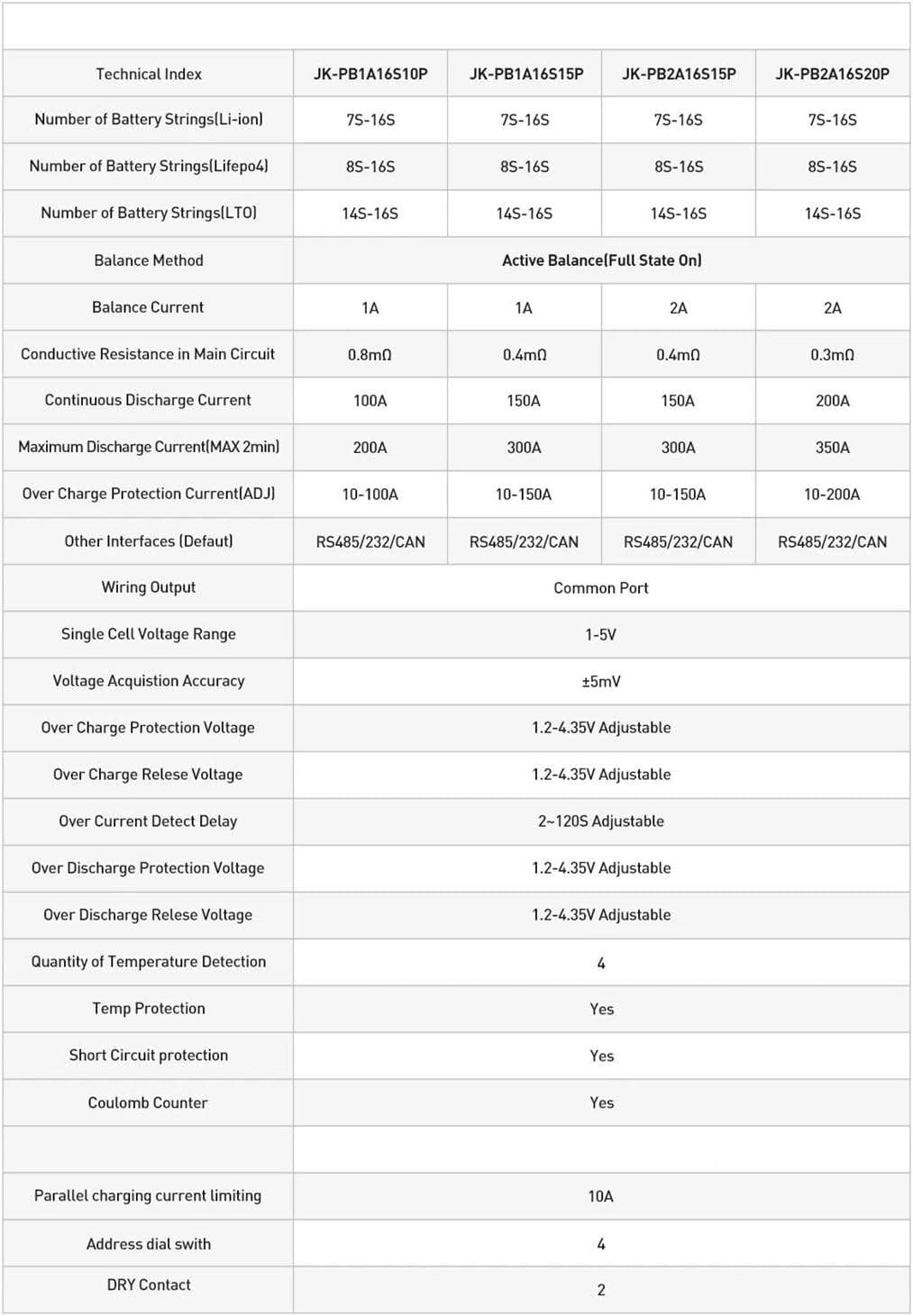
Figure 8.1: Detailed technical index comparing various JK-PB series BMS models, including the JK-PB2A16S15P.
| Technical Index | JK-PB2A16S15P |
|---|---|
| Number of Battery Strings (Li-ion) | 7S-16S |
| Number of Battery Strings (Lifepo4) | 8S-16S |
| Number of Battery Strings (LTO) | 14S-16S |
| Balance Method | Active Balance (Full State On) |
| Balance Current | 2A |
| Conductive Resistance in Main Circuit | 0.4mΩ |
| Continuous Discharge Current | 150A |
| Maximum Discharge Current (MAX 2min) | 300A |
| Over Charge Protection Current (ADJ) | 10-150A |
| Other Interfaces (Default) | RS485/232/CAN |
| Wiring Output | Common Port |
| Single Cell Voltage Range | 1-5V |
| Voltage Acquisition Accuracy | ±5mV |
| Over Charge Protection Voltage | 1.2-4.35V Adjustable |
| Over Charge Release Voltage | 1.2-4.35V Adjustable |
| Over Current Detect Delay | 2-120S Adjustable |
| Over Discharge Protection Voltage | 1.2-4.35V Adjustable |
| Over Discharge Release Voltage | 1.2-4.35V Adjustable |
| Quantity of Temperature Detection | 4 |
| Temp Protection | Yes |
| Short Circuit protection | Yes |
| Coulomb Counter | Yes |
| Parallel charging current limiting | 10A |
| Address dial swith | 4 |
| DRY Contact | 2 |
9. Warranty and Support
For warranty information and technical support, please refer to the documentation included with your purchase or visit the official KACOME website. Keep your proof of purchase for warranty claims. If you encounter any issues not covered in this manual, please contact KACOME customer service for expert assistance.