
KURNMQNZ FST100-ZD103
Firstrate FST100-ZD103 Turbidity Sensor User Manual
Industry Water Quality Monitor RS485 Intelligent Turbidity Sensor Probe
1. Introduction
This user manual provides comprehensive instructions for the installation, operation, maintenance, and troubleshooting of the Firstrate FST100-ZD103 Industry Water Quality Monitor. This intelligent turbidity sensor probe is designed for accurate measurement of water quality in industrial applications, featuring RS485 communication and a resolution of 0.1 NTU.
Please read this manual thoroughly before using the device to ensure proper functionality and safety.
2. Safety Information
Observe the following safety precautions to prevent damage to the device or injury to personnel:
- Ensure all electrical connections comply with local regulations.
- Do not attempt to disassemble or repair the sensor unless explicitly instructed by qualified personnel.
- Protect the sensor from extreme temperatures, corrosive substances, and physical impact.
- Always disconnect power before performing any maintenance or installation procedures.
3. Product Specifications
The Firstrate FST100-ZD103 turbidity sensor features robust design and precise measurement capabilities. Key specifications are detailed below:
| Parameter | Value |
|---|---|
| Measuring Range | 0-100 NTU (customizable) |
| Resolution | 0.1 NTU |
| Accuracy | ±1% FS |
| Operating Temperature | 0°C ~ 50°C |
| Case Material | Stainless Steel |
| Installation Method | Flow-through, Submersible |
| Signal Line Length | 5m (customizable) |
| Protection Level | IP68 |
| Output | 4~20mA and RS485 |
4. Components and Overview
The FST100-ZD103 sensor consists of the main probe body, signal cable, and connection points. Familiarize yourself with the components before installation.
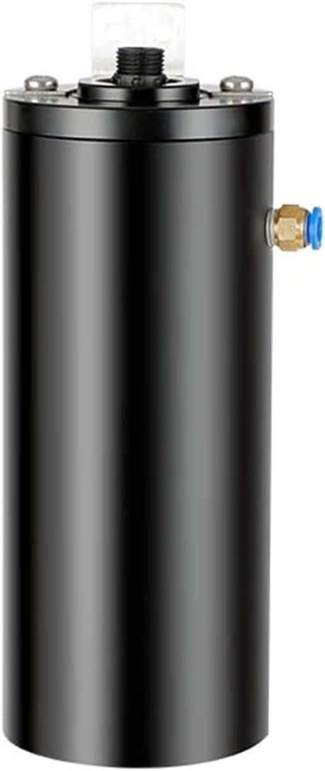
This image displays the primary cylindrical body of the FST100-ZD103 turbidity sensor, with visible connection points on the top surface and a side port for water flow.

This image shows the FST100-ZD103 sensor from an angled perspective, revealing the integrated mounting bracket at one end and the electrical connector.

This image provides a side view of the FST100-ZD103 sensor, emphasizing its compact cylindrical design and the blue quick-connect fitting.
5. Setup and Installation
Proper installation is crucial for accurate and reliable measurements. The FST100-ZD103 supports both flow-through and submersible installation methods.
5.1 Electrical Connections
The sensor utilizes an RS485 interface and also provides a 4-20mA analog output. Ensure correct wiring to your control system or data logger.
- Power Supply: Connect the sensor to a stable DC power source (refer to specifications for voltage range).
- RS485 Communication: Connect the A and B terminals of the sensor to the corresponding RS485 A and B terminals on your controller. Ensure proper termination resistors if required by your RS485 network.
- 4-20mA Output: Connect the analog output terminals to the 4-20mA input of your PLC or data acquisition system.
- Grounding: Ensure proper grounding to prevent electrical interference.
5.2 Mechanical Installation
Choose the appropriate installation method based on your application requirements.
5.2.1 Flow-Through Installation
For inline measurement in pipes or conduits:
- Integrate the sensor into the pipeline using appropriate fittings.
- Ensure the flow direction is consistent with the sensor's design (if applicable).
- Verify all connections are watertight and secure to prevent leaks.
5.2.2 Submersible Installation
For direct immersion in tanks, open channels, or reservoirs:
- Use the provided mounting bracket to secure the sensor in the desired location.
- Ensure the sensor is fully submerged and positioned away from air bubbles or stagnant zones.
- Protect the signal cable from physical damage and ensure it is properly routed.
6. Operating Instructions
Once installed and powered, the FST100-ZD103 sensor will begin measuring turbidity. Data can be read via the RS485 interface or the 4-20mA analog output.
6.1 Data Acquisition via RS485
The sensor communicates using the Modbus RTU protocol over RS485. Refer to the Modbus communication protocol document (not included in this manual) for specific register addresses and commands.
- Baud Rate: Typically 9600 bps (configurable).
- Data Bits: 8
- Parity: None
- Stop Bits: 1
- Slave ID: Configurable (default often 1).
Use a compatible Modbus master device (e.g., PLC, HMI, or PC with RS485 converter) to read turbidity values from the sensor.
6.2 Data Acquisition via 4-20mA Output
The 4-20mA output provides an analog signal proportional to the measured turbidity. This output can be directly connected to analog input modules of PLCs or data loggers.
- 4mA typically corresponds to 0 NTU.
- 20mA typically corresponds to the full scale of the measuring range (e.g., 100 NTU).
- Ensure your receiving device is calibrated to interpret the 4-20mA signal correctly.
7. Maintenance
Regular maintenance ensures the longevity and accuracy of the FST100-ZD103 sensor.
7.1 Cleaning the Sensor Probe
Biofouling or sediment accumulation on the sensor's optical window can affect measurement accuracy.
- Disconnect power to the sensor before cleaning.
- Carefully remove the sensor from its installation point.
- Gently wipe the optical window with a soft, lint-free cloth or brush. For stubborn deposits, use a mild, non-abrasive cleaning solution.
- Rinse the sensor with clean water and dry it before reinstallation.
- Avoid scratching the optical surface.
7.2 Calibration
While the sensor is factory calibrated, periodic field calibration may be necessary depending on application requirements and regulatory standards. Refer to the sensor's specific calibration procedure (often performed via the RS485 interface or a dedicated controller) for detailed steps.
Use certified turbidity standards for accurate calibration.
7.3 Cable Inspection
Periodically inspect the signal cable for any signs of wear, cuts, or damage. Damaged cables can lead to signal loss or electrical hazards. Replace damaged cables immediately.
8. Troubleshooting
This section provides solutions to common issues encountered during the operation of the FST100-ZD103 sensor.
| Problem | Possible Cause | Solution |
|---|---|---|
| No Reading / Incorrect Reading |
|
|
| RS485 Communication Error |
|
|
| 4-20mA Output Incorrect |
|
|
9. Warranty Information
The Firstrate FST100-ZD103 sensor is covered by a standard manufacturer's warranty against defects in materials and workmanship. The warranty period typically begins from the date of purchase. Please retain your proof of purchase for warranty claims.
This warranty does not cover damage resulting from improper installation, misuse, unauthorized modification, or natural disasters. For specific warranty terms and conditions, please refer to the documentation provided with your purchase or contact KURNMQNZ customer support.
10. Technical Support
For technical assistance, troubleshooting beyond this manual, or inquiries regarding spare parts and accessories, please contact KURNMQNZ technical support.
Contact Information:
- Website: Visit KURNMQNZ on Amazon (for general product information)
- Email: Refer to your purchase documentation for direct support email.
- Phone: Refer to your purchase documentation for direct support phone number.
When contacting support, please have your product model (FST100-ZD103) and purchase details ready.
no relevant documents
Ask a question about this manual
Ask about setup, troubleshooting, compatibility, parts, safety, or missing instructions. Manuals+ will review the question and use this page’s manual context to help answer it.